


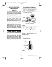
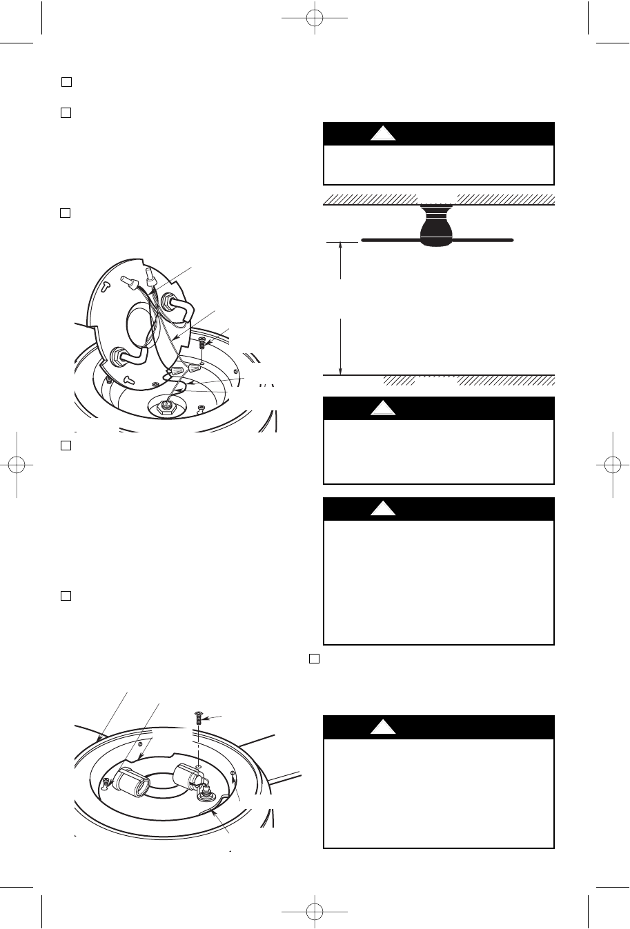
CEILING
FLOOR
AT
LEAST
7'
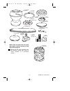
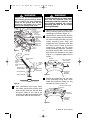
Figure 5
6
UL Model No.: CF144 & CF152
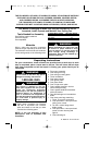
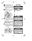
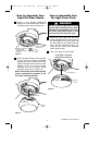
9. Tuck the wires and connectors into the
fan housing. Position the light kit plate
into the fan housing by placing the cut
out notches over the fan housing
dimples (Figure 4).
10. Attach the light kit plate assembly to
the lower housing using two key slot
holes (Figure 4). Secure the light kit
plate assembly by tightening the two
screws. Reinstall the screw that was
previously removed.
1. Disconnect electrical power to the branch
circuit at the circuit breaker or fuse box
before attempting to install the ceiling fan
mounting plate on the outlet box.
NOTE: Make sure all wires and
connectors are tucked under the light
kit plate and not pinched between light
kit plate and fan housing.
REMOVE M4 x 10mm
PAN HEAD SCREW
KEY HOLE SLOT (2)
LOWER HOUSING
LIGHT KIT
PLATE
DIMPLES
CUT OUT
NOTCHES
Figure 4
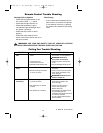
How to Hang
Your Ceiling Fan
The fan must be hung with at least 7' of
clearance from floor to blades (Figure 5).
!
WARNING
The outlet box and joist must be securely
mounted and capable of supporting at
least 50 lbs. Use only a U.L. outlet box
listed as “Acceptable for Fan Support”.
!
WARNING
To reduce the risk of fire, electric shock,
or personal injury, mount fan to outlet box
marked “Acceptable for Fan Support”,
and use screws supplied with outlet box.
Most outlet boxes commonly used for
support of light fixtures are not
acceptable for fan support and may need
to be replaced. Consult a qualified
electrician if in doubt.
!
WARNING
Turning off wall switch is not sufficient.
To avoid possible electrical shock, be sure
electricity is turned off at the main fuse or
circuit breaker box before wiring. All wiring
must be in accordance with National and
Local codes and the ceiling fan must be
properly grounded as a precaution against
possible electrical shock.
!
WARNING
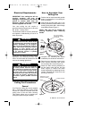
6. Remove and retain the wire connectors
from the white and blue wires.
7. Connect the white wire from the ceiling
fan to the white wire of the light kit plate
(Figure 3). Connect the blue wire from
the ceiling fan to the black wire of the
light kit plate. Use wire connectors
(previously removed) to make
connections.
8. Remove one of the three screws in the
lower housing and loosen the
remaining two screws (Figure 3).
LIGHT KIT
BLACK WIRE
LIGHT KIT
WHITE WIRE
FAN MOTOR
WHITE WIRE
REMOVE ONE
LOWER HOUSING
SCREW
FAN MOTOR
BLUE WIRE
Figure 3
BP7407 44" & 52" Curva Sky 1/11/10 9:54 PM Page 6