August 2015
6
Quick Start Guide
Note
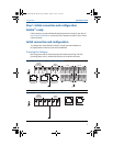
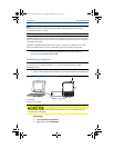
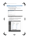
Figure 1 depicts the terminal block of legacy Gateways prior to the introduction of PoE capabilities.
Figure 2 shows the terminal block arrangement of a PoE version of the Gateway. If the Gateway will
be powered via the standard 24 volt power input terminals, and no PSE is desired, it is not
necessary to change the default settings of the PoE jumper matrix.
Note
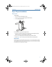
The Gateway enclosure case should always grounded in accordance with national and local
electrical codes. The most effective grounding method is a direct connection to earth ground with
minimal impedance.
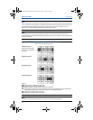
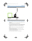
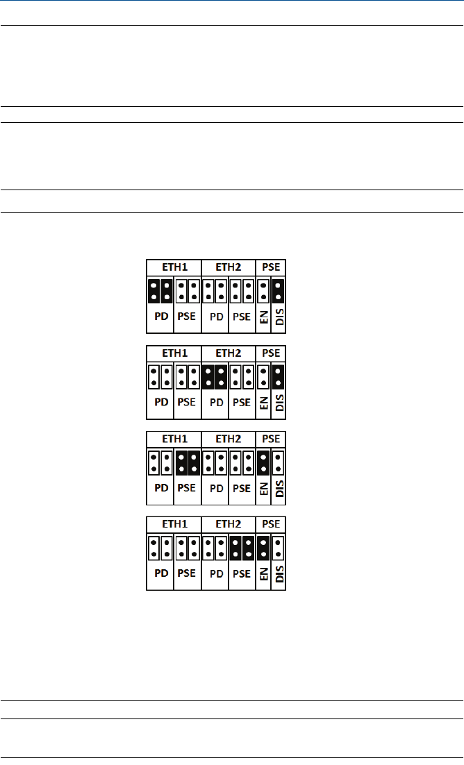
Figure 3. 1420 PoE Jumpering Matrix (Located on 1420 Board)
Legend:
ETH1: Ethernet port 1 selected for PD or PSE
ETH2: Ethernet port 2 selected for PD or PSE
PD: Gateway derived its power off the Ethernet port selected
PSE: The Gateway is powered via the standard 24 volt power input terminals and provides power
via the selected Ethernet port to another device with a compatible PD port.
EN: Enabled; this enables the PSE operation
DIS: Disabled; this disables the PSE operation
Note
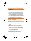
Electrostatic discharge (ESD) protection required when swapping PoE jumpers.
PoE PD on port 1
(Default jumpering for
production. Used for no
PoE also)
PoE PD on port 2
PoE PSE on port 1
PoE PSE on port 2
Black fill below indicates jumper.
00825-0200-4420_RevFE.fm Page 6 Monday, August 10, 2015 3:25 AM


