


August 2015
16
Quick Start Guide
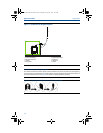
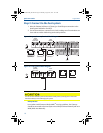
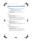
Step 3: Connect to the host system
1. Wire the Gateway’s Ethernet 1 (Primary) or Serial Output connection to the
Host System Network or Serial I/O.
2. For serial connections, connect A to A, B to B, making sure all terminations are
clean and secured to avoid wiring connection problems.
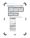
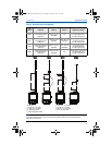
Figure 9. Legacy Gateway Terminal Block Diagram
Figure 10. PoE Terminal Block Diagram
Best practice
In accordance with Emerson WirelessHART
®
security guidelines, the Gateway
should be connected to the Host System via a LAN (Local Area Network) and not a
WAN (Wide Area Network).
Do not connect the Host System to the Ethernet 2 with power (covered) port on the Smart
Wireless Gateway to avoid damaging the system.
+
+
+
+
+
-
-
-
-
-
AB
S
S
S
S
24 VDC
(nominal)
Power Input
Serial
Modbus
N
ot Used
Not Use
d
N
ot Use
d
Not Use
d
Case
(Covered)
S
Ethernet 2
with Power
Ethernet 2
Ethernet 1
(Secondary) (Primary)
+
-AB
24 VDC
(nominal)
Power Input
Serial
Modbus
Case
S
Ethernet 2
Ethernet 1
(Secondary) (Primary)
00825-0200-4420_RevFE.fm Page 16 Monday, August 10, 2015 3:25 AM