


Table of Contents
Unit I GENERAL INFORMATION ................................... 1
DESCRIPTION ............................................................... 1
FEATURES .................................................................. 1
CONTROLLER SPECIFICATIONS................................................ 1
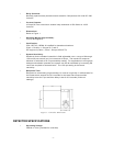
Figure 1 - Controller Dimensions ........................................... 2
DETECTOR SPECIFICATIONS ........................................... 2
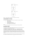
Figure 2b - Swivel Mount Dimensions ....................................... 3
Figure 2a - Detector Dimensions ........................................... 3
BASIC OPERATION - CONTROLLER ............................................. 4
CONTROLLER FACEPLATE DESCRIPTION ................................. 4
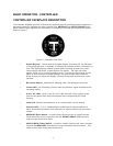
Figure 3 - Controller Face-Plate ............................................ 4
OUTPUTS ............................................................ 5
Table 1 - Selectable Output Options ........................................ 5
Figure 4 - Jumper Selection for Isolated or Non-Isolated Current Outputs . . . . . . . . . . . 5
PROGRAMMING OPTIONS .............................................. 6
EXTERNAL RESET ..................................................... 6
AUTOMATIC DIAGNOSTICS AND FAULT IDENTIFICATION . . . . . . . . . . . . . . . . . . . . 6
VOTING LOGIC (not applicable to U1F) ..................................... 7
DETECTOR.................................................................. 7
Unit II UV FIRE DETECTION ...................................... 7
SYSTEM APPLICATION........................................................ 7
DETECTOR SENSITIVITY ...................................................... 8
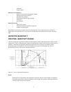
SPECTRAL SENSITIVITY RANGE ......................................... 8
Figure 5 - Various Spectral Distributions ..................................... 8
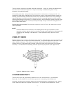
CONE OF ............................................................ 9
VI SION ............................................................... 9
Figure 6 - Detector Cone of Vision .......................................... 9
SYSTEM SENSITIVITY......................................................... 9
Unit III SYSTEM INSTALLATION .................................. 10
INSTALLATION.............................................................. 10
GENERAL WIRING REQUIREMENTS ..................................... 10
CONTROLLER WIRING ................................................ 10
Figure 7a - Wiring for U1F-UV with Non-Isolated Current Output . . . . . . . . . . . . . . . . . 12
Figure 7b - Wiring for U1F-UV with Isolated Current Output . . . . . . . . . . . . . . . . . . . . . 13
Figure 8a - Wiring for U2F-UV with Non-Isolated Output . . . . . . . . . . . . . . . . . . . . . . . . 14
Figure 8b - Wiring Diagram for U2F-UV with Isolated Current Output . . . . . . . . . . . . . . 15
Figure 9a - Wiring for U4F-UV with Non-Isolated Current Output . . . . . . . . . . . . . . . . . 16
Figure 9b - Wiring for U4F-UV with Isolated Current Output . . . . . . . . . . . . . . . . . . . . . 17
POSITION AND DENSITY OF DETECTORS....................................... 18
MOUNTING THE DETECTOR ........................................... 18
Figure 10 - Detector with Swivel Mount Assembly . . . . . . . . . . . . . . . . . . . . . . . . . . . . 18
DIP SWITCH SETTINGS ...................................................... 18
Figure 11b - Dip Switch ................................................. 19
Figure 11a - Dip Switch Position .......................................... 19
CHANNEL SELECTION................................................. 19
CONTROLLER SENSITIVITY ADJUSTMENT . . . . . . . . . . . . . . . . . . . . . . . . . . . . . . . 19
FIRE AREA VOTING SEQUENCE (not applicable to U1F) . . . . . . . . . . . . . . . . . . . . . . 20
RELAY OUTPUTS LATCHING/NON-LATCHING . . . . . . . . . . . . . . . . . . . . . . . . . . . . . 20
RELAY OUTPUTS ENERGIZED/DE-ENERGIZED . . . . . . . . . . . . . . . . . . . . . . . . . . . . 20
TIME DELAY FOR AREA ALARMS........................................ 21
RELAY SETTINGS ........................................................... 21
Figure 11c - Relay Position .............................................. 21
Figure 11d - Relay Settings .............................................. 21