


- 27 -
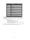
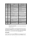
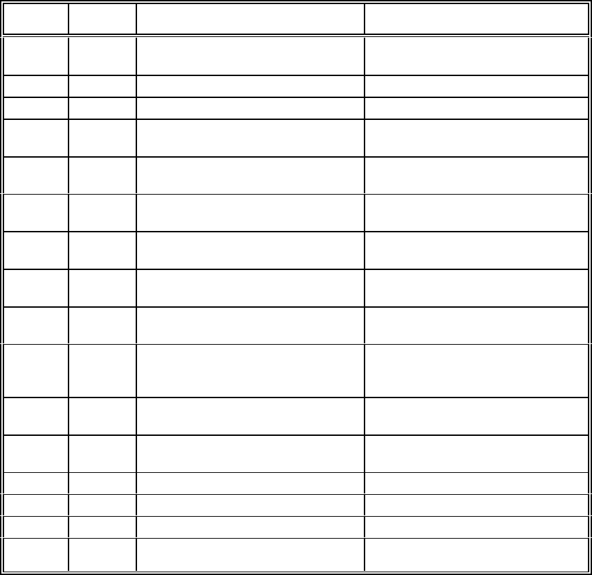
LEFT
DISPLAY
RIGHT
DISPLAY ERROR WHAT TO DO
290 gnd
Grounding problem with detector
290 Vdc supply.
Check wiring to detector, 290Vdc
may be shorted to ground.
290 OLo
+290 Vdc detector power too low. Contact Factory.
290 OHi
+290 Vdc detector power too high. Contact Factory.
12 OUT
Internal 12 Vdc supply out of
operating range.
1
Recycle power and call factory if
problem persists.
5 OUT
Internal 5 Vdc supply out of
operating range.
1
Recycle power and call factory if
problem persists.
24H OUT
Controller supply is greater than
32Vdc.
Check your power supply.
24L OUT
Controller 24 Vdc supply is less
than 18Vdc.
Check your power supply.
ch OiH
Visual integrity error (Signal
received is too high).
Contact Factory.
chx OiL
2
Visual integrity error (Signal
received is too low).
Clean detector window and
reflector.
rSt E71
Reset Reed Switch is damaged, or
has been activated for more than 15
seconds.
Make sure no magnetic objects are
in close proximity to the switch.
Ert Err
External reset switch short error. Make sure external reset switch is
not damaged or shorted to ground.
CFg Err
Configuration error; incorrect dip
switch settings.
Check dip switch settings and
recycle power.
E91 Err
System RAM error. Contact Factory.
E92 Err
Power is not stable. Contact Factory.
E94 Err
EEPROM data not correct. Contact Factory.
E97 Err
EEPROM reading, or writing not
correct.
Contact Factory.
Table 3 - Error Codes
1 If an internal power supply problem occurs, recycle power to the controller. If the
problem persists, contact supplier.
2 If more than one channel has a vi error, the upper display will sequentially show
each channel number.
If a fault has occurred, but no longer exists, the fault LED will remain illuminated and the displays
will alternate between ‘nor’ and ‘Err Fnd’. To find out what the fault was, enter the error check
mode by keeping the MENU/SET switch activated until ‘Chc Err’ is displayed, then activating the
SELECT/RESET switch. The display should now show ‘dSP Err’. Activate the SELECT/RESET
switch and the fault error codes are sequentially displayed. Once all faults have been displayed,
‘Clr Err’ is displayed. To clear the fault codes, activate the SELECT/RESET switch.
MAIN MENU
The main menu is entered by activating the MENU/SET switch for approximately 5 seconds until
‘Chc’ ‘Err’ or ‘bPS’ is shown on the displays. Repeatedly activating the MENU/SET switch will
toggle through the selections. When the desired selection is shown on the displays, activate the