


- 18 -
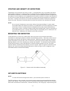
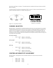
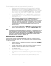
Figure 10 - Detector with Swivel Mount Assembly
POSITION AND DENSITY OF DETECTORS
The detector has a nominal 120º cone of vision. In an application such as a loading rack with a
ceiling height of 25 feet (7.5 meters) where it is desired to have complete detector coverage at
floor level and a detector is mounted 2 feet (0.6 meter) from the ceiling and pointed straight down,
the distance from the detector to the designated level would be 23 feet (7 meters) and because of
its 120º cone of vision the detector would cover a circular area 80 feet (24 meters) in diameter at
floor level. A sketch of the area to be covered will indicate the number of detectors required to
monitor the area. Detectors should be placed as close as practical to the expected fire hazard.
NOTE
Do not mount UV detectors close to the ceiling of enclosed buildings if smoke might
accumulate before the break-out of flame. It is preferable to mount the detectors on walls
a few feet (or about 1 meter) below the ceiling where they may respond before being
obscured by smoke. Consider shortening time delay settings when smoke is expected to
accumulate during a fire. If dense smoke is likely to accumulate prior to flame (as in an
electrical fire), supplement UV detectors with other protection.
MOUNTING THE DETECTOR
Locate detectors to ensure an unobstructed view of the area to be monitored and where
accessible for cleaning the detector window and vi reflecting surface. Take care so dirt will not
accumulate and obscure the detector viewing window. Detectors mounted outdoors should be
pointed downward to prevent the cone of vision from scanning the horizon where long duration
lightning flashes or far-off arc welding may activate the detector. To minimize dirt accumulation
around the vi surfaces, mount the detectors so that the internal vi tube is on top. The silver
external reflector should be placed directly over the vi tube. Refer to Figures 2a and 2b for the
detector and swivel mounting assembly dimensions. Refer to Figure 10 for a diagram of the
assembled detector and swivel assembly.
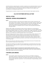
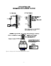
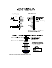
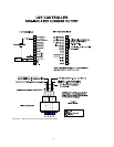
DIP SWITCH SETTINGS
NOTE
To make DIP switch changes take effect, cycle controller power off then on.
The DIP switches on the controller circuit board must be properly programmed before applying
power to the system. There are three banks of 8 position DIP switches which are OFF or ON to
select area and detector combinations, controller sensitivity, fire voting logic, output latching and