


- 25 -
ALTERNATE TEST PROCEDURE
After each channel is offered for selection in the bypass mode a final ‘test bPS’ selection is
offered. All channels are now in the test bypass mode. In this mode the counts per second,
normally seen when a channel is in bypass, are not seen and the Channel, Instant, and Area
LEDs will operate as they would in the normal operating mode (ie. flash when a fire condition
exists etc.), but the relay and current outputs are inhibited. This is an excellent way to test sensor
sensitivity settings and to assure that if a fire occurs the controller will respond. Activate the
SELECT/RESET switch, while in this mode, to return to the normal operating mode.\
NORMAL OPERATION
FIRE RESPONSE
When the controller receives a ‘fire’ signal from any detector in the system, it is compared to the
stored information of the program. If the signal level is greater than the programmed sensitivity
setting:
1. The instant alarm relay and the appropriate current output change status and the
instant LED flashes.
2. The left side of the display cycles through all detectors responding to the fire
(CH1, CH2, CH3, or CH4).
3. The right side of the digital display indicates a fire (‘Fir’).
4. One or more channel LEDs turn on (blinking), indicating the channel(s) detecting
UV radiation.
If the signal level is greater than the programmed sensitivity setting for longer than the preset time
delay and the selected ‘voting’ criteria has been satisfied, the appropriate Area outputs change
status and the corresponding Area LED is flashing. The bar graph display is also flashing.
NOTE
When a fire signal is no longer present, the channel LED(s) and the instant and area LEDs will be
latched on until manually reset (LEDs are on, but no longer flashing).
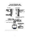
Current Outputs
4-20 mA DC current outputs transmit system information to other devices. The current outputs
can be wired for isolated or non-isolated operation by changing a jumper connection as shown in
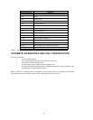
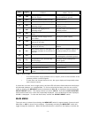
Figure 4. The current output can have a maximum external loop resistance of 600 ohms. Table 2
shows the current output levels for various situations.