


8
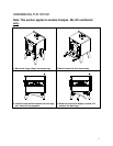
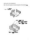
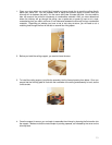
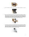
INSTALLATION OF A HEAT RADIATION SHIELD
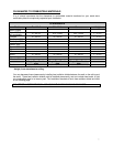
Following the installation of a heat radiation shield, the clearances mentioned on the stove certification plate
may be reduced as stated in the following table.
Reductions in clearance to a combustible wall (or
ceiling) and the heating device, %
TYPE OF PROTECTION
SIDES AND
REAR\BACK
TOP
Minimal requirements:
0,013" (0,33 mm) sheet metal
with 1" (25.4mm) fire-proof braces
67%** 50%
Ceramic tile or an equivalent fire-proof material
resting on fire-proof brackets spaced 1" (25.4mm)
apart by fire-proof braces
50% 33%
Ceramic tile or an equivalent fire-proof material built
on a fire-proof base resting on sheet metal of at
least 0,013" (0,33 mm) thick spaced 1" (25.4mm)
by fire-proof braces.
67% 50%
Solid bricks, spaced 1" (25.4mm) from the rear
wall using fire-proof braces.
50% N\A
Solid bricks, resting on sheet metal 0,013" (0,33
mm) thick spaced 1" (25.4mm) from the rear wall
using fire-proof braces.
67% N\A
**Example: 15 inches x (100% - 67%) = 4,95 inches.
This reduction in clearance, when in compliance, is accepted by insurance companies.
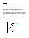
FOR BARON 2000SP USING THE ENVELOPE
It is strictly forbidden to connect the envelope to existing liners or existing floor registers
or grilles.