


www.desatech.com
108661-01F
16
FIREPLACE INSTALLATION
Continued
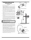
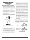
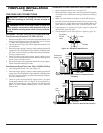
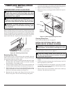
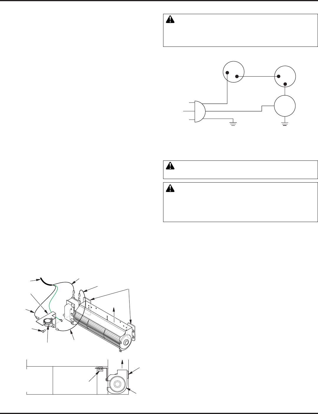
Figure 29 - Blower Wiring Diagram for Thermostat-Controlled
Models
Blower Wiring Diagram
when servicing controls. Wiring errors can cause im-
proper and dangerous operation. Verify proper opera-
tion after servicing.
3. Place the blower against the lower rear wall of the rebox outer
wrapper with the exhaust port directed upward and the thermo-
disc positioned up near the replace bottom. The thermodisc
must be oriented near the replace bottom as shown in Figure 28
in order to sense temperature and properly operate. The blower
will be held in position against the back wall by the magnets
incorporated onto the blower housing (see Figure 28).
4. Be certain that all wire terminals are securely attached to ter-
minals on blower motor and thermal switch, and that the screw
for the thermodisc bracket and green ground wire is tight.
5. Mount the speed control box against the mounting plate provided
in the lower replace cavity by placing the plastic control shaft
forward through the round hole (see Figure 26, page 15).
6. While supporting speed control, secure control shaft with lock
nut by pushing and turning lock nut with pliers clockwise until
it is tight against mounting plate. Place control knob provided
on shaft (see Figure 26, page 15).
7. Check to make sure that the power cord is completely clear of
the blower wheel and that there are no other foreign objects in
blower wheel. Also double check all wire leads and make sure
wire routing is not pinched or in a precarious position. Correct
accordingly.
8. Turn on power to duplex outlet if previously turned off per the
warning in column 2, page 14.
9. Plug in blower power cord to duplex outlet.
10. The blower will only run when the speed control knob is in the
ON position and the thermal switch senses temperature after the
replace begins to heat up. The blower speed can be adjusted by
rotating the control knob. To turn off, turn knob fully counterclock-
wise until it clicks off. If the blower is ON and has been running
with the replace operating, the blower will continue to run for a
short time after the replace has been turned off. As the thermal
switch cools down, the blower shuts down automatically.
11. Peel off the backing paper and stick the supplied wiring diagram
decal on the rebox bottom approximately 12" in front of the
blower (see Figure 27, page 15).
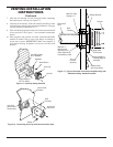
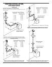
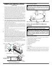
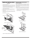
Thermodisc
Figure 28 - Blower Model BKT
Air Flow Direction
Route BKT Blower
Through This Area
Magnets
Blower
Location
Side View Firebox Bottom
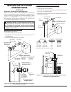
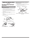
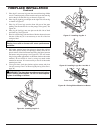
Black
Wire
Phillips
Screw
Blue Wire
Ring Terminal
on Green Wire
White Wire
Thermal Switch
Thermal
Switch
Bracket
Power Cord
Air Flow
Direction
Magnetic
Strips
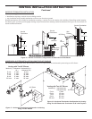
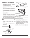
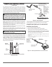
requires an external regulator (not supplied). Install
-
pane/LP supply.
Installation Items Needed
Before installing replace, make sure you have the items listed below.
• external regulator (supplied by installer)
• piping (check local codes)
• sealant (resistant to propane/LP gas)
• equipment shutoff valve *
• test gauge connection *
• sediment trap
• tee joint
• pipe wrench
• approved exible gas line with gas connector (if allowed by local
codes)
* A CSA design-certied equipment shutoff valve with 1/8" NPT tap
is an acceptable alternative to test gauge connection. Purchase the
CSA design-certied equipment shutoff valve from your retailer.
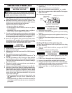
Blue
Variable
Fan Switch
Fan Switch
(N.O.)
Green
White
On
110/115
V.A.C.
Blower
Motor
Black
Off
1
2
Black