


www.desatech.com
111251-01E 29
OPERATING FIREPLACE
Continued
TO TURN OFF GAS
TO APPLIANCE
1. Turnoffthewallswitch.
2. Turn off all electric power to the appliance
if service is to be performed.
3. Open lower louver panel.
4. Turn equipment shutoff valve clockwise
to OFF. Do not force.
5. Close lower louver panel.
OPTIONAL REMOTE
OPERATION
Note: TheWRCreceiverandhand-heldre-
motecontrolkitmustbepurchasedseparately
(see Accessories, page 39). Follow installation
instructions on page 28.
1. TurnequipmentshutoffvalvetoONposi-
tion.Youcannowturntheburneronand
off with the hand-held remote control unit.
IMPORTANT:BesuretopresstheON/OFF
buttons on the hand-held remote control
unit for up to 3 seconds to assure proper
operation.
2. Press the ON/OFF buttonto turnthe
burner on and off.
OPERATING OPTIONAL
Locatetheblowercontrolsbyopeningthelower
louverpanelonthereplace.Blowercontrols
are located on the left side of the switch bracket
to the left just inside the louver panel.
TheBKmanualblowerandtheBKTthermo-
statically-controlledblowerhaveanONsetting
andanOFFsetting.Theblowerwillonlyrun
when the switch is in the ON position. In the
OFF position, the blower will not operate.
IfyouareusingBKT
blower with optional thermostat (wall mounted
orremotecontrol)forthereplace,yourre-
place and blower will not turn on and off at the
sametime.Thereplacemayrunforseveral
minutes before the blower turns on. After the
heater modulates to the pilot position, the blow-
er will continue to run. The blower will shut off
afterthereboxtemperaturedecreases.
The blower helps distribute heated air from
thereplace.Periodicallycheckthelouversof
thereboxandremoveanydust,dirt,orother
obstructionsthatwillhindertheowofair.
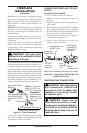
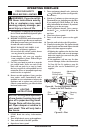
INSPECTING BURNERS
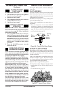
Check pilot ame pattern and burner ame pat-
terns often.
The pilot assembly is factory preset for the proper
ame. Alterations may have occurred during ship-
ping and handling. The pilot is located on the back
right hand side of the burner.
The ame must envelope 1/4" of top of the ignitor/
sensor and grounding stem.
If your pilot assembly does not meet these re-
quirements:
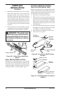
• Turn the adjustment screw marked PILOT
clockwise to decrease or counterclockwise to
increase the ame to proper size (see Figure 48,
page 28). Do not remove the adjustment screw.
• see Troubleshooting, page 31
Pilot
Burner
Ignitor/
Sensor
Figure 50 - Correct Pilot Flame Pattern
Sensing
Rod
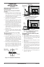
Burner ames will be steady; not lifting or oating.
Flame patterns will be different from unit to unit
and will vary depending on installation type and
weather conditions.
If the vent conguration is installed incorrectly,
the ames will lift or "ghost". This can be danger-
ous. Inspect the ames after installation to ensure
proper installation and performance.
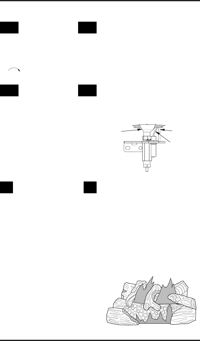
Figure 51 shows a typical ame pattern.
If burner ame pattern differs from that described:
• turn replace off (see To Turn Off Gas to Ap-
pliance)
• see Troubleshooting, page 31
Figure 51 - Typical Flame Pattern