


www.desatech.com
111251-01E 21
FIREPLACE
INSTALLATION
Continued
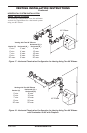
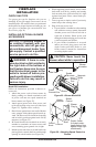
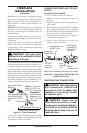
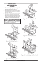
Figure 31 - Gas Connection
CSA Design-Certied
Equipment Shutoff
Valve with 1/8" NPT
Tap*
3" Minimum
Approved Flexible
Gas Line
Cap Pipe Nipple Tee Joint
Sediment Trap/Drip Leg
Natural - From Gas
Meter (5.5" W.C. to
10.5" W.C. Pressure)
* The CSA design-certied equipment shutoff
valve may be supplied with the appliance or you
can purchase it from your retailer.
Propane/LP
From External
Regulator (11"
W.C. to 14" W.C.
Pressure)
Installation must include an equipment shutoff
valve, union, and plugged 1/8" NPT tap. Locate
NPT tap within reach for test gauge hook up.
NPT tap must be upstream from replace (see
Figure 31).
IMPORTANT: Install main gas valve (equipment
shutoff valve) in an accessible location. The main
gas valve is for turning on or shutting off the gas
to the appliance.
Check your building codes for any special re-
quirements for locating equipment shutoff valve
to replaces.
Apply pipe joint sealant lightly to male NPT
threads. This will prevent excess sealant from
going into pipe. Excess sealant in pipe could result
in clogged replace valves.
We recommend that you install a sediment trap/
drip leg in supply line as shown in Figure 31. Lo-
cate sediment trap/drip leg where it is within reach
for cleaning. Install in piping system between fuel
supply and replace. Locate sediment trap/drip leg
where trapped matter is not likely to freeze. A sedi-
ment trap traps moisture and contaminants. This
keeps them from going into replace gas controls.
If sediment trap/drip leg is not installed or is in-
stalled wrong, replace may not run properly.
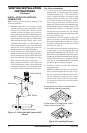
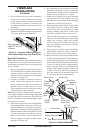
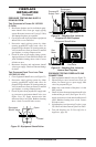
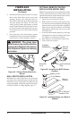
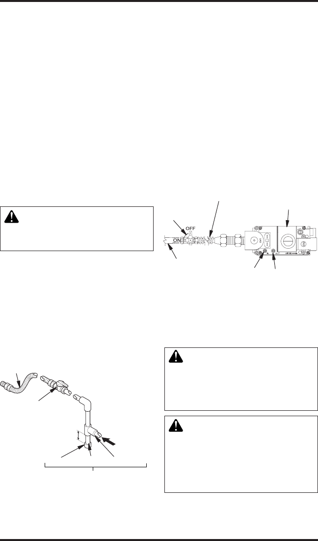
Figure 32 - Connecting Flexible Gas Line
to Electronic Valve
1/2" NPT
Incoming
Gas Line
Inlet
Pressure
Tap
Outlet
Pressure Tap
Equipment
Shutoff Valve
Flexible Gas Line
Do NOT Kink
Note: Wire Connections Not Shown for Clarity
Red Surface
Indicates For
Propane/LP
Use Only
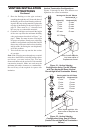
CONNECTING FIREPLACE TO GAS
SUPPLY
Installation Items Needed
• 5/16" hex socket wrench or nut-driver
• sealant (resistant to propane/LP gas, not
provided)
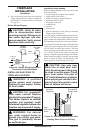
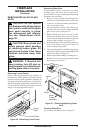
1. Open lower louver door panel by gently pull-
ing forward.
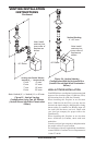
2. Route exible gas line (provided by installer)
from equipment shutoff valve to replace.
Route exible gas supply line through one of
the access holes on side of replace.
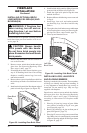
3. Attach exible gas line from gas supply to
control valve (see Figure 32).
4. Check all gas connections for leaks. See
Checking Gas Connections.
and connections, internal and
external to unit, for leaks after
WARNING: Never use an
-