


www.desatech.com
116412-01B 21
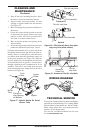
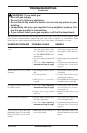
1. Shut off the unit, including the pilot. Allow
the unit to cool for at least thirty minutes.
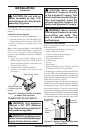
2. Inspect burner, pilot and primary air inlet
opening on injector holder for dust and dirt
(see Figure 27).
3. Blow air through the ports/slots and holes in
the burner.
4. Check the injector holder located at the end
of the burner tube again. Remove any large
particles of dust, dirt, lint or pet hair with a
soft cloth or vacuum cleaner nozzle.
5. Blow air into the primary air opening on the
injector holder.
6. In case any large clumps of dust have now been
pushed into the burner repeat steps 3 and 4.
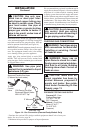
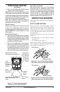
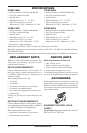
Clean the pilot assembly also. A yellow tip on the
pilot ame indicates dust and dirt in the pilot as-
sembly. There is a small pilot air inlet hole about
two inches from where the pilot ame comes out
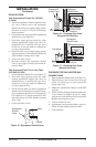
of the pilot assembly (see Figure 28). With the
unit off, lightly blow air through the air inlet hole
in the same direction as gas ow. You may blow
through a drinking straw if compressed air is not
available. This hole is accessible from the front
of the unit through an L-shaped hole in the valve
bracket (see Figure 29).
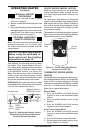
Figure 27 - Injector Holder On Outlet
Burner Tube
Burner
Tube
Injector
Holder
Injector
Primary Air
Inlet Opening
(At Bottom)
Ports
Slots
CLEANING AND
MAINTENANCE
Continued
Figure 28 - Pilot Inlet Air Hole (Your pilot
may vary from pilots shown)
Pilot Assembly
Pilot Air Inlet Hole
Pilot Assembly
Pilot Air Inlet Hole
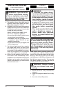
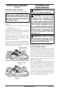
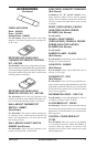
WIRING DIAGRAM
Natural
A
U
T
O
O
F
F
ON
Thermopile
Figure 29 - Access to Pilot Air Inlet Hole
O
FF
P
I
LO
T
O
N
Pilot Air
Inlet Hole
Access to
Clean Pilot
TECHNICAL SERVICE
You may have further questions about installation,
operation or troubleshooting. If so, contact DESA
Technical Service Department at 1-866-672-6040.
When calling please have your model and serial
numbers of your heater ready.
You can also visit DESA technical services web
site at .