


www.desatech.com
112108-01C 11
VENTING INSTALLATION
INSTRUCTIONS
Continued
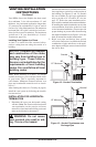
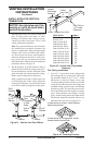
Your DESA direct-vent replace has been tested
for a minimum 3' rise with a maximum 11" wall
thickness. Any horizontal application longer than
12" must provide a minimum of 1 foot of vertical
rise for every 3 feet of horizontal run. The maximum
horizontal run is 20' with 8' vertical rise (see Instal-
lation for Horizontal Termination). The maximum
vertical run is 30' (see Installation for Vertical
Termination, page 114).
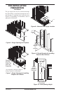
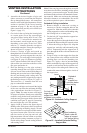
A chase is a vertical box-like structure built to
enclose venting that runs along the outside of a
building.
and construction of the chase
-
Note: When installing in a chase, you should
insulate the chase as you would the outside walls
of your home. This is especially important in
cold climates. Minimum clearance between vent
pipes and combustible materials such as insula-
tion is 1".
After framing the chase (see Framing on page 6)
install the vent system by following the installa-
tion instructions.
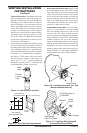
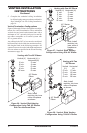
INSTALLATION FOR HORIZONTAL
TERMINATION
1. Determine the route your horizontal venting
will take. Note: The location of the horizontal
vent termination on the exterior wall must
meet all local and national building codes and
must not be blocked or obstructed.
WARNING: Do not recess
vent terminal into a wall or sid-
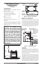
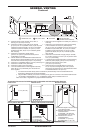
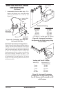
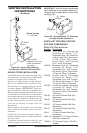
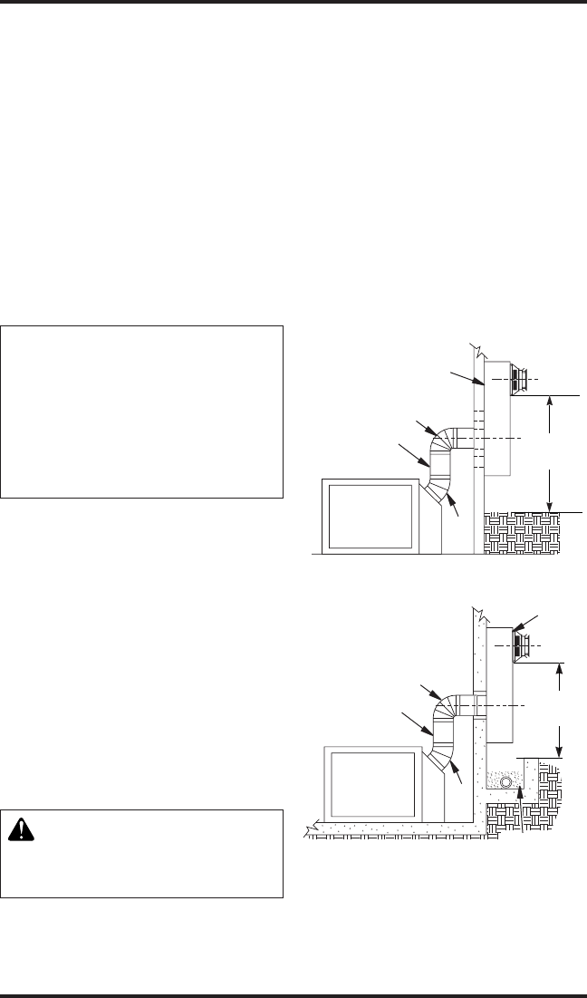
Snorkel terminations are available for termina-
tions requiring a vertical rise on the exterior of
the building (see Figures 12 and 13). Snorkel
kits are available for rigid pipe applications
only to provide a 14" rise and a 36" rise (see
page 17). Follow the same installation proce-
dures used for standard horizontal terminations.
If installing the snorkel termination to raise the
vent termination from below grade level such
as in a basement installation, you must provide
proper drainage to prevent water from entering
the snorkel termination (see Figure 13). Do not
back ll around the snorkel termination.
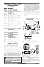
2. Rigid vent pipes and ttings have special
twist-lock connections. Assemble the desired
combination of pipe and elbows to the appli-
ance adaptor with pipe seams oriented towards
the wall or oor.
Figure 13 - Snorkel Termination with
Drainage Pipe
Figure 12 - Snorkel Termination
Snorkel
12" Minimum
90º
45º
Adequate
Drainage
Snorkel
12" Minimum
90º
45°
12"
Minimum
12"
Minimum