


www.desatech.com
55511E 7
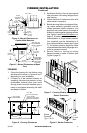
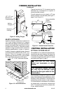
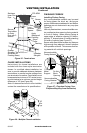
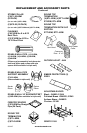
Figure 13 - Pipe Connection
GAIN
368STM See-Through 66
1
/
4
"
V368ST See-Through 54
"
(V)12-8DM Flue Pipe 10
5
/
8
"
(V)18-8DM Flue Pipe 16
5
/
8
"
(V)24-8DM Flue Pipe 23
5
/
8
"
(V)36-8DM Flue Pipe 34
5
/
8
"
(V)48-8DM Flue Pipe 46
5
/
8
"
VRTL-8DM
VRTTL-8DM
Round Top
Termination
6"
VETL-8M
VETO-8DM
VETLO-8DM
Econo-Top
Termination
1
" to 12"
Hemmed
End
8" Stainless
Inner Pipe
Lanced Side
Up
12
3
/
8
" Galvanized
Outer Pipe
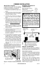
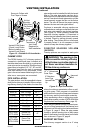
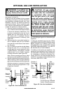
Figure 12 - Outside Air Kit Installation
Secure to Collars with
Duct Tape or Screws
Air Inlet
Location
Must Allow
For Bushes
or Snow
Vent Hood
Required for
Wall Installation
Air Inlet
Termination
Vented Crawl Space
(Check Local Codes
Before Installing in a
Vented Crawl Space)
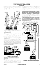
The DESA Heating, LLC chimney system is
a snap-lock, double-wall pipe. It consists of a
stainless steel inner ue pipe(s), a galvanized
outer pipe and a wire spacer. Each section of
pipe comes in lengths of 12", 18", 36" and 48".
The actual lineal gain for each is measured
after each section is fully connected. Lineal
gain is the actual measurable length of a part
after two or more parts are connected.
The pipe sections must be assembled indepen-
dently as the chimney is installed. When connect-
ing chimney directly to the rebox, the inner ue
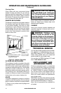
VENTING INSTALLATION
Continued
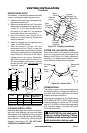
where the chimney penetrates a oor or ceil-
ing joist space. Their purpose is to establish
and maintain the required clearance between
the chimney and the combustible materials.
When penetrating a oor or ceiling at an angle,
use restop spacer number V30FS-8DM (see
Replacement and Accessory Parts, page 14).
When the pipe passes through a framed open-
ing into a living space above, the restop must
be placed onto the ceiling from below as shown
in Figure 14, page 8. When the pipe passes
through a framed opening into an attic space
above, the restop must be placed on the attic
oor as shown in Figure 15, page 8.
The chimney support section is a 4" strap
pipe section must be installed rst with the lanced
side up. The outer pipe section can then be in-
stalled over the ue pipe section with the hemmed
end up. Press down on each pipe section until the
lances securely engage the hem on the rebox
starter. The wire will assure the proper spacing
between the inner and outer pipe sections.
Continue to assemble chimney sections as
outlined above, making sure that both the inner
and outer pipe sections are locked together
(see Figure 13). When installing double wall
snap-lock chimney together, it is important to
assure the joint between the chimney sections
is locked. Check by pulling chimney upward
after locking. The chimney will not come apart
if properly locked. It is not necessary to add
screws to keep the chimney together.
Firestop spacers are required at each point
collar around the chimney at the top
-
ed. Never use blown insulation to