


www.desatech.com
11389
6-01A
16
INSTALLATION
Continued
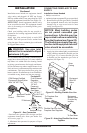
Installation must include an equipment shutoff
valve, union, and plugged 1/8" NPT tap. Locate
NPT tap within reach for test gauge hook up. NPT
tap must be upstream from heater (see Figure 21).
IMPORTANT: Install equipment shutoff valve
in an accessible location. The equipment shutoff
valve is for turning on or shutting off the gas to
the appliance.
Check your building codes for any special re
-
quirements for locating equipment shutoff valve
to fireplaces.
Apply pipe joint sealant lightly to male NPT
threads. This will prevent excess sealant from
going into pipe. Excess sealant in pipe could result
in clogged heater valves.
WARNING: Use pipe joint
sealant that is resistant to liquid
petroleum (LP) gas.
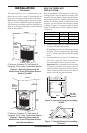
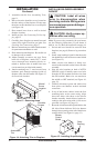
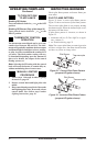
We recommend that you install a sediment trap in
supply line as shown in Figure 21. Locate sediment
trap where it is within reach for cleaning. Install
in piping system between fuel supply and heater.
Locate sediment trap where trapped matter is not
likely to freeze. A sediment trap traps moisture and
contaminants. This keeps them from going into
heater controls. If sediment trap is not installed or
is installed wrong, heater may not run properly.
* Purchase the optional CSA design-certified
equipment shutoff valve from your dealer. See
Accessories, page 32.
** Minimum inlet pressure for purpose of input
adjustment.
3" Minimum
Gas
Control
Propane/LP
From External
Regulator
(11" W.C.** to
14" W.C.
Pressure)
Natural From
Gas Meter
(5" W.C.**
to 10.5" W.C.
Pressure)
CSA Design-Certified
Equipment Shutoff Valve
With 1/8" NPT Tap*
Approved Flexible
Gas Hose
Figure 21 - Gas Connection
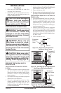
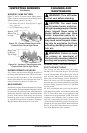
Cap Pipe Tee
Nipple Joint
Sediment Trap
A
U
T
O
O
F
F
O
N
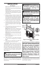
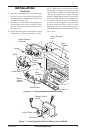
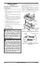
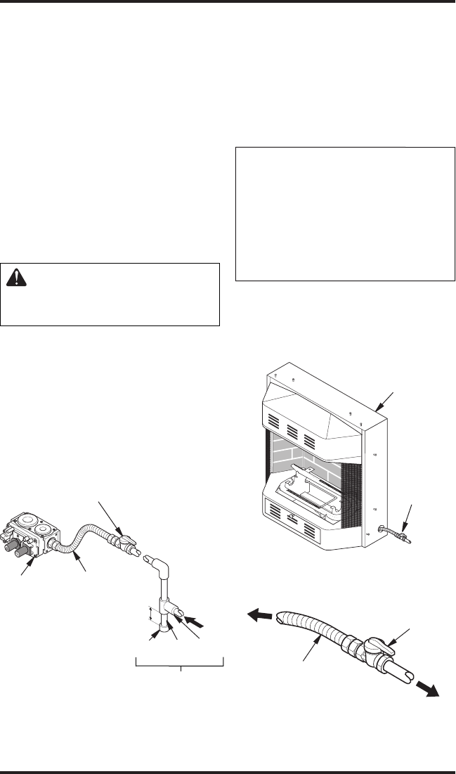
Figure 22 - Routing Flexible Gas Line
Equipment
Shut Off
Valve
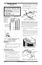
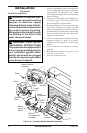
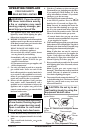
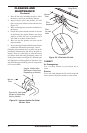
Figure 23 - Attaching Flexible Gas Lines
Together
Outer
Casing
CONNECTING FIREPLACE TO GAS
SUPPLY
Installation Items Needed
• Phillips screwdriver
•
sealant (resistant to propane/LP gas, not provided)
1. Route flexible gas line (provided by installer)
from equipment shutoff valve into fireplace
through side or rear access holes in outer
casing (see Figure 22).
NOTICE: Most building codes
do not permit concealed gas
connections. A flexible gas line
is provided to allow accessibility
from the fireplace (see Figure 23).
The flexible gas supply line con-
nection to the equipment shutoff
valve should be accessible.
2. Apply pipe joint sealant lightly to male threads
of gas connector attached to flexible gas line
(see Figure 23). Connect flexible gas line
to flexible gas line attached to gas valve of
fireplace (see Figure 23).
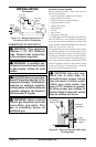
Flexible Gas Line from
Fireplace Gas Regulator
To Fireplace Gas
Regulator
Equipment
Shutoff Valve
Provided by
Installer
To Gas Meter