


www.desatech.com
11389
6-01A 17
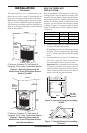
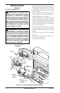
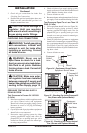
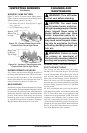
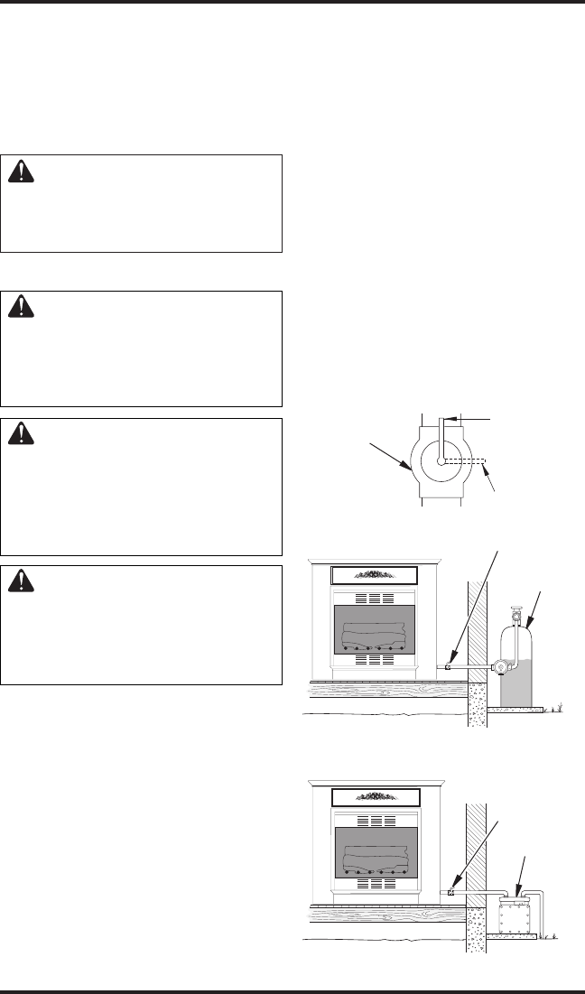
Figure 24 - Equipment Shutoff Valve
Open
Closed
Equipment
Shutoff
Valve
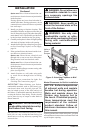
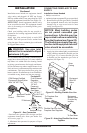
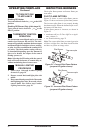
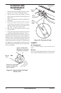
Figure 26 - Checking Gas Joints Natural
Gas (Shown with Optional Mantel)
Gas Meter
Equipment
Shutoff Valve
INSTALLATION
Continued
3. Check all gas connections for leaks. See
Checking Gas Connections.
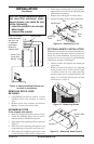
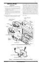
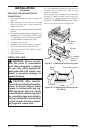
4. Feed flexible gas line into fireplace base area.
Make sure the entire flexible gas line is in
fireplace mantel base area.
CAUTION: Avoid damage to
regulator. Hold gas regulator
with wrench when connecting it
to gas piping and/or fittings.
CHECKING GAS CONNECTIONS
WARNING: Test all gas piping
and connections, internal and
external to unit, for leaks after
installing or servicing. Correct
all leaks at once.
WARNING: Never use an
open flame to check for a leak.
Apply a noncorrosive leak detec
-
tion fluid to all joints. Bubbles
forming show a leak. Correct all
leaks at once.
CAUTION: Make sure exter-
nal regulator has been installed
between propane/LP supply and
heater. See guidelines under Con
-
necting to Gas Supply, page 15.
PRESSURE TESTING GAS SUPPLY
PIPING SYSTEM
Test Pressures In Excess Of 1/2 PSIG
(3.5 kPa)
1. Disconnect appliance with its appliance main
gas valve (control valve) and equipment
shutoff valve from gas supply piping system.
Pressures in excess of 1/2 psig will damage
heater regulator.
2. Cap off open end of gas pipe where equipment
shutoff valve was connected.
3. Pressurize supply piping system by either
opening propane/LP supply tank valve for
propane/LP gas or opening main gas valve
located on or near gas meter for natural gas,
or using compressed air.
4. Check all joints of gas supply piping system.
Apply noncorrosive leak detection fluid to all
joints. Bubbles forming show a leak.
5. Correct all leaks at once.
6.
Reconnect heater and equipment shutoff valve to
gas supply. Check reconnected fittings for leaks.
Test Pressures Equal To or Less Than 1/2
PSIG (3.5 kPa)
1. Close equipment shutoff valve (see Figure 24).
2. Pressurize supply piping system by either
opening propane/LP supply tank valve for
propane/LP gas or opening main gas valve
located on or near gas meter for natural gas,
or using compressed air.
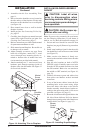
3. Check all joints from gas meter to equipment
shutoff valve for natural gas or propane/LP sup
-
ply to equipment shutoff valve for propane/LP
(see Figures 25 and 26). Apply noncorrosive
leak detection fluid to all joints. Bubbles form
-
ing show a leak.
4. Correct all leaks at once.
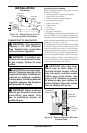
Figure 25 - Checking Gas Joints Propane/LP
Gas (Shown with Optional Mantel)
Equipment Shutoff Valve
Propane/LP
Supply Tank