


www.desatech.com
11389
6-01A 11
INSTALLATION
Continued
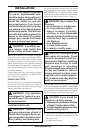
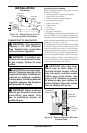
13"
16"
19"
21"
2
1
/
2
"
6"
8"
10"
Minimum Non-
Combustible
Material
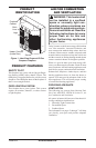
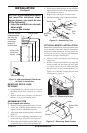
Figure 9 - Minimum Mantel Clearances
for Built-In Installation
Mantel Shelf
Note: All vertical
measurements
are from top
of fireplace
opening to
bottom of
mantel shelf.
REMOVING BRICK LINER
RETAINER
1. Using Phillips screw driver, remove 2 screws
attaching brick liner retainers to vertical
sides.
2. Remove brick liner retainers and discard.
Replace 2 screws into vertical sides.
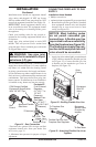
ASSEMBLING TRIM
(Trim shipped with mantel)
1. Remove packaging from three pieces of trim.
2. Locate two adjusting plates with set screws,
and two shims in the hardware packet.
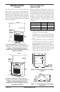
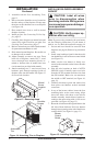
3. Align shim under adjusting plate as shown in
Figure 10.
4. Slide one end of adjusting plate/shim in slot
on mitered edge of top trim (see Figure 10).
5. Slide other end of adjusting plate/shim in slot
on mitered edge of side trim (see Figure 10).
Figure 10 - Assembling Trim
Top
Trim
Side
Trim
Mitered
Edge
Shim
Set Screws
Adjusting
Plate
Slot
Slot
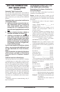
OPTIONAL MANTEL INSTALLATION
Note: Refer to instructions provided with the man-
tel for assembly instructions. Refer to instructions
below for system installation. If using blower ac-
cessory (see Accessories, page 32), see installation
instructions on pages 12 through 15.
1. Choose location for fireplace and install gas
supply line.
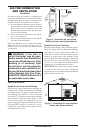
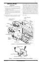
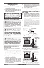
2. Remove screen from fireplace by removing
screws in each end of screen rod (see Figure
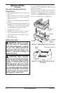
11). Hold screen rod cover while removing
five hex head screws underneath hood (see
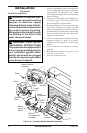
Figure 12). Carefully lift and pull out hood
(see Figure 13, page 12).
A
U
T
O
O
F
F
ON
Figure 11 - Removing Screen
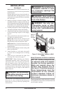
Figure 12 - Removing Hood Screws
Hood
Screen Rod
Cover
Screw
NOTICE: If your installation does
not meet the minimum clear-
ances shown, you must do one
of the following:
• raise the mantel to an accept-
able height
• remove the mantel
6. While firmly holding edges of trim together,
tighten both set screws on the adjusting plate
with slotted screwdriver.
7. Repeat steps 1 through 6 for other corner.
8. Set trim assembly aside for later installation.