


www.desatech.com
113084-01E 13
INSTALLATION
Continued
CAUTION: Avoid damage to
regulator. Hold gas regulator
with wrench when connecting it
to gas piping and/or ttings.
* Purchase the optional CSA design-certified
equipment shutoff valve from your dealer. See
Accessories, page 27.
** Minimum inlet pressure for purpose of input
adjustment.
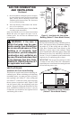
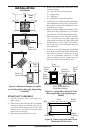
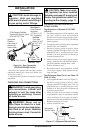
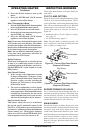
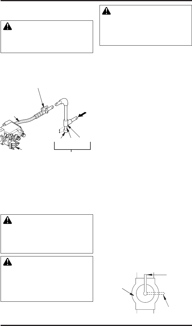
Figure 16 - Gas Connection
(SVYD18PRA/NRA Series)
3” Min
Sediment Trap
Gas Control
CSA Design-Certied
Equipment Shutoff Valve
With 1/8" NPT Tap*
Approved
Flexible
Gas Hose (if
allowed by
local codes)
Cap Pipe Tee
Nipple Joint
PROPANE/LP
From External
Regulator
(11" W.C. to 14"
W.C. Pressure)
NATURAL
From Gas
Meter (5” W.C.
to 10.5” W.C.
Pressure)
CHECKING GAS CONNECTIONS
WARNING: Test all gas piping
and connections, internal and
external to unit, for leaks after
installing or servicing. Correct
all leaks at once.
WARNING: Never use an
open ame to check for a leak.
Apply a noncorrosive leak detec-
tion uid to all joints. Bubbles
forming show a leak. Correct all
leaks at once.
CAUTION: Make sure exter-
nal regulator has been installed
between propane/LP supply and
heater. See guidelines under Con-
necting to Gas Supply, page 11.
PRESSURE TESTING GAS SUPPLY
PIPING SYSTEM
Test Pressures In Excess Of 1/2 PSIG
(3.5 kPa)
1. Disconnect appliance with its appliance main
gas valve (control valve) and equipment
shutoff valve from gas supply piping system.
Pressures in excess of 1/2 psig will damage
heater regulator.
2. Cap off open end of gas pipe where equipment
shutoff valve was connected.
3. Pressurize supply piping system by either
opening propane/LP supply tank valve for
propane/LP gas or opening main gas valve
located on or near gas meter for natural gas
or using compressed air.
4. Check all joints of gas supply piping system.
Apply a noncorrosive leak detection uid to
gas joints. Bubbles forming show a leak.
5. Correct all leaks at once.
6.
Reconnect heater and equipment shutoff
valve to gas supply. Check reconnected t-
tings for leaks.
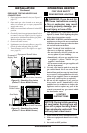
Test Pressures Equal To or Less Than 1/2
PSIG (3.5 kPa)
1.
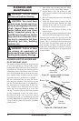
Close equipment shutoff valve (see Figure 17).
2. Pressurize supply piping system by either
opening propane/LP supply tank valve for
propane/LP gas or opening main gas valve
located on or near gas meter for natural gas
or using compressed air.
3. Check all joints from gas meter for natural
or propane/LP supply to equipment shutoff
valve (see Figure 18 or 19, page 14). Apply a
noncorrosive leak detection uid to gas joints.
Bubbles forming show a leak.
4. Correct all leaks at once.
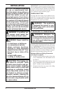
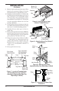
Figure 17 - Equipment Shutoff Valve
Equipment
Shutoff Valve
Closed
Open