


www.desatech.com
108795-01V20
TO TURN OFF GAS
TO APPLIANCE
1. Turn off wall switch.
2. Turn off all electric power to appliance if
service is to be performed.
3. Fully open glass doors if installed.
4. Remove front hearth brick and control
access panel.
5. Turn gas control knob clockwise
to OFF. Do not force.
6. Replace front refractory brick access
panel.
7. Fully close glass doors if installed.
OPERATION
Continued
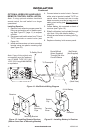
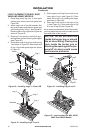
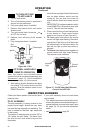
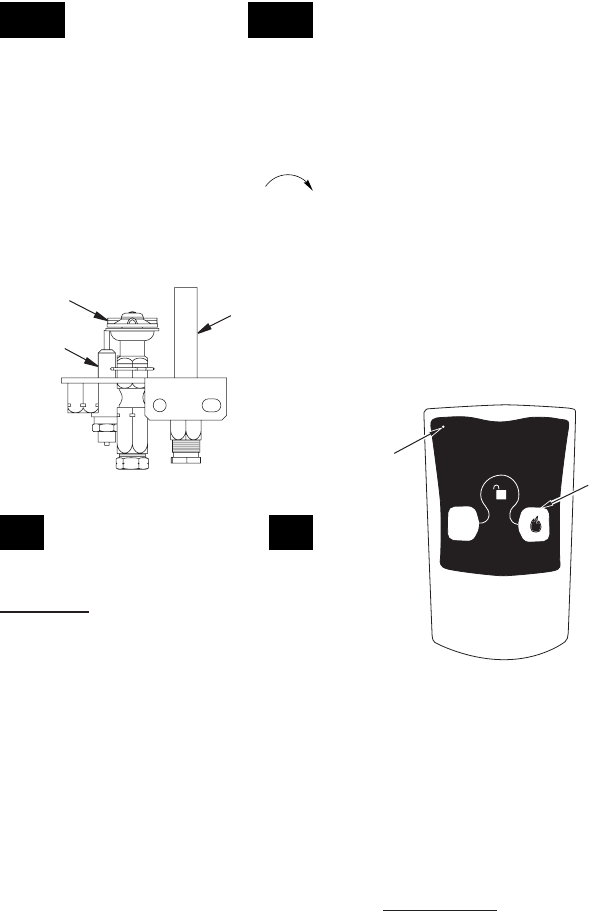
Figure 40 - Pilot
Thermopile
Pilot
Burner
Ignitor
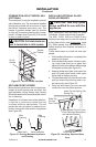
Figure 41 - On/Off Hand-Held Remote
Control Unit HRC100
Control
Button
Indicator
Light
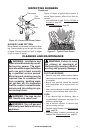
INSPECTING BURNERS
OPTIONAL HAND-HELD
REMOTE OPERATION
Note: The receiver and hand-held remote
control kit must be purchased separately (see
Accessories, page 31). Follow installation
instructions on page 10 of this manual.
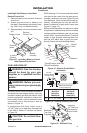
1. After lighting, let pilot ame burn for about
one minute. Turn control knob to the ON
position. Slide the selector switch to the
REMOTE position.
Note: Burner may light if hand-held remote
was on when selector switch was last
turned off. You can now turn burner on
and off with the hand-held remote control
unit.
IMPORTANT: Do not leave selector switch
in the REMOTE or ON position when pilot
is not lit. This will drain the battery.
2. Press control button on hand-held remote
to turn burner on. Press control button
again to turn burner off (see Figure 41).
3. ToLock press both buttons on remote
control until light stops ashing. Remote is
now locked. If the re is on it will be turned
off automatically. In the locked state, the
light will not light up when any button is
pressed.
4. ToUnlock press both buttons together on
remote control until light stops ashing.
The remote is now unlocked.
Check pilot ame pattern and burner ame
patterns often.
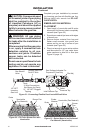
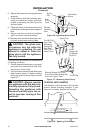
PILOT ASSEMBLY
The pilot assembly is factory preset for the
proper ame height. Alterations may have
occurred during shipping and handling. The
pilot is located on the back right hand side
of the burner.
The height of the thermopile must be 3/8" to
1/2" above the pilot ame. The ame from
the pilot burner must extend beyond the
thermopile.
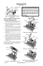
If your pilot assembly does not meet these
requirements:
• Turn adjustment screw marked pilot clock-
wise to decrease or counterclockwise to in-
crease the ame to proper size (see Figure
39, page 19). Do not remove adjustment
screw.
• see Troubleshooting, page 23