


www.desatech.com
108795-01V 7
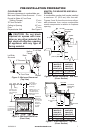
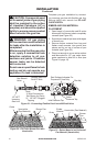
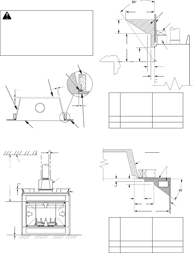
PRE-INSTALLATION PREPARATION
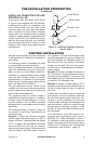
Figure 3 - Minimum Clearances
(Top View)
0"
0" Clearance
Nailing
Flange
Front Face
Left Side
Surround
Back
Drywall
2 x 4 Stud
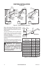
Figure 4 - Minimum Clearances
(Front View)
*
*
**
42" (106.7 cm)
Min. Clearance
from Opening to
Ceiling
0" Clearance
Ceiling
1" (2.5 cm)
Min. Clearance
to "B" Vent's
Outer Pipe
Maintain 2" (5.1 cm)
Min. Clearance to
Transition Pipe as
Measured at Outer
V e nt Collar
Required air
spaces are
indicated with
an "
*
". Do not
pack with
insulation or
any other
material.
DO NOT BLOCK
OR OBSTRUCT
OPENINGS
0" Clearance to
Combustible or
Noncombustible
Flooring
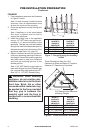
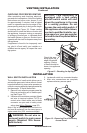
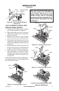
MANTEL CLEARANCES AND WALL
DETAILS
A combustible mantle shelf maybe installed
a maximum 12" (22.9 cm) from the wall.
Figures 5 and 6 show the minimum allow-
able distances from various combustible
mantle components in relation to fireplace
opening.
Spacer
3" (7.6 cm)
1
1
/
2
"
(3.8 cm) Max.
B
6" (15.2 cm)
A
12"
(22.9 cm)
Combustible
Materials
Header
Figure 5 - Mantel Clearances - Side View
(Cross Section)
M36(B,H),
M36P(B,H)
VM36(B,H),
VM36P(B,H)
M42(B,H),
M42P(B,H)
VM42(B,H),
VM42P(B,H)
A 14" (35.6 cm) 15" (38 cm)
B 8" (20.3 cm) 9" (22.9 cm)
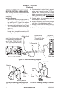
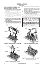
1
1
/
2
"
(3.8 cm)
Max.
3" (7.6 cm)
Max.
6" (15.2 cm)
Max.
A
B
Outer Surround
Combustible
Material May
Be Used
TOP VIEW
SAFE
ZONE
Perpendicular
Wall
Figure 6 - Side Clearances - Top View
(Cross Section)
CLEARANCES
Minimum clearances to combustibles are:
Back and Sides of Outer Surround 0" min.
Drywall to Sides of Front Face
(Nailing Flanges) 0" min.
“B” Vent Surfaces 1" min.
Ceiling to Opening 42" min.
Floor 0" min.
Perpendicular Wall See Figure 6
CAUTION: Do not block
required airspaces withinsu-
lationoranyothermaterial.Do
notobstruct effectiveopening
of appliance with any type of
facingmaterial.
M36(B,H),
M36P(B,H)
VM36(B,H),
VM36P(B,H)
M42(B,H),
M42P(B,H)
VM42(B,H),
VM42P(B,H)
A 9" (22.9 cm) 6" (15.2 cm)
B 12" (30.5 cm) 9" (22.9 cm)