


www.desatech.com
119508-01A6
ASSEMBLY
Continued
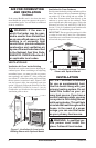
AIR FOR COMBUSTION
AND VENTILATION
WARNING: This heater shall
-
-
Today’s homes are built more energy efficient
than ever. New materials, increased insulation and
new construction methods help reduce heat loss in
homes. Home owners weather strip and caulk around
windows and doors to keep the cold air out and the
warm air in. During heating months, home owners
want their homes as airtight as possible.
While it is good to make your home energy ef-
cient, your home needs to breathe. Fresh air must
enter your home. All fuel-burning appliances need
fresh air for proper combustion and ventilation.
Exhaust fans, replaces, clothes dryers and fuel
burning appliances draw air from the house to
operate. You must provide adequate fresh air for
these appliances. This will insure proper venting
of vented fuel-burning appliances.
The following are excerpts from National Fuel Gas
Code, ANSI Z223.1/NFPA 54, Section 5.3, Air for
Combustion and Ventilation.
All spaces in homes fall into one of the three fol-
lowing ventilation classications:
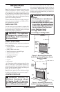
1. Unusually Tight Construction
2. Unconned Space
3. Conned Space
The information on pages 6 through 8 will help
you classify your space and provide adequate
ventilation.
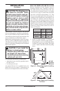
The air that leaks around doors and windows
may provide enough fresh air for combustion and
ventilation. However, in buildings of unusually
tight construction, you must provide additional
fresh air.
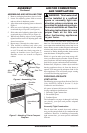
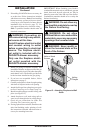
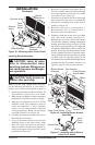
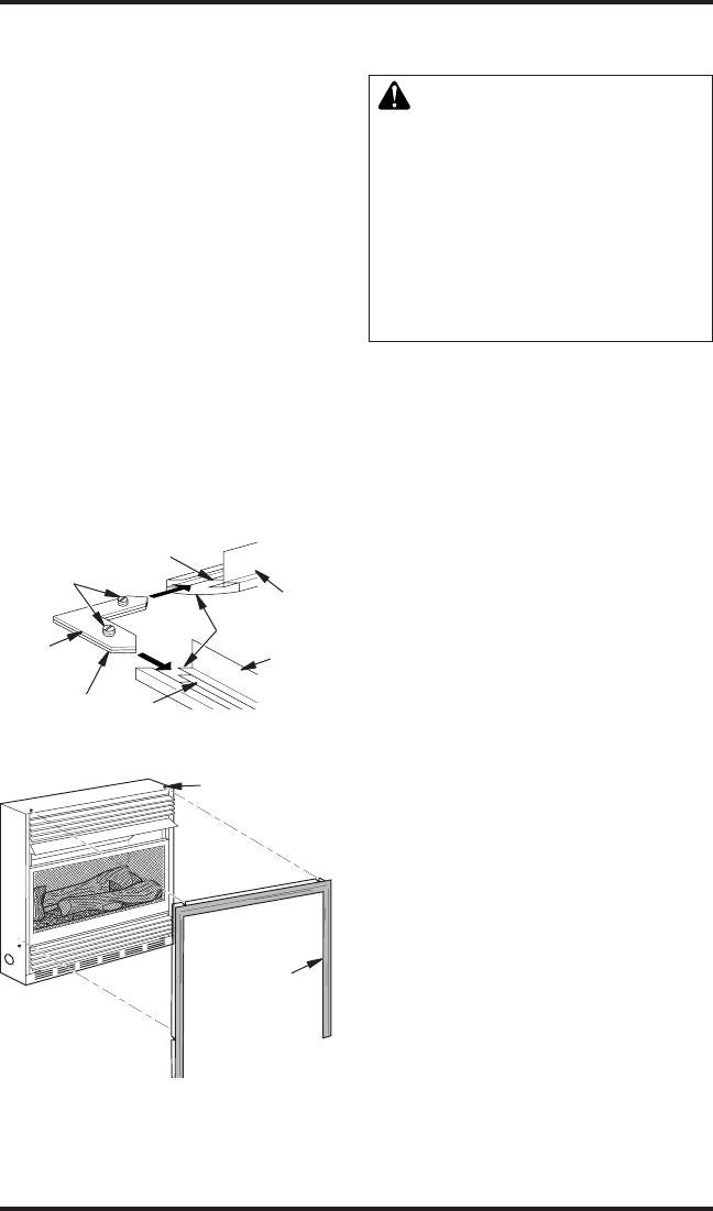
ASSEMBLING AND INSTALLING TRIM
1. Remove packaging from three pieces of trim.
2. Locate two adjusting plates with set screws
and two shims in hardware packet.
3. Align shim under adjusting plate as shown in
Figure 4.
4. Slide one end of adjusting plate/shim in slot
on mitered edge of top trim (see Figure 4).
5. Slide other end of adjusting plate/shim in slot
on mitered edge of side trim (see Figure 4).
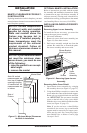
6. While rmly holding edges of trim together,
tighten both set screws on adjusting plate with
slotted screwdriver.
7. Repeat steps 2 through 6 or other corner.
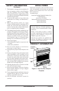
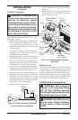
8. Trim should be attached only after your
replace has been installed into the mantel
or wall. To install trim, rmly snap trim as-
sembly on shoulder screws (see Figure 5).
Shoulder screws are located on replace
cabinet.
Figure 4 - Assembling Trim
Top Trim
Mitered Edge
Side Trim
Slot
Shim
Adjusting
Plate
Set
Screws
Slot
Figure 5 - Attaching Trim to Compact
Fireplace
Assembled
Trim
Shoulder
Screw