


8
CAST IRON STOVE AND BURNER SYSTEM
107600
For more information, visit www.desatech.com
CAST IRON STOVE
AND B-VENT
BURNER SYSTEM
ASSEMBLY
Continued
WARNING: Never touch the
blower wheel while in operation.
NOTICE: If installing blower in an
existing stove burner system with
gas connections, shut off gas sup-
ply and disconnect burner sys-
tem from gas supply. Contact a
qualified service person to do this.
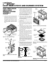
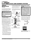
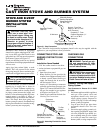
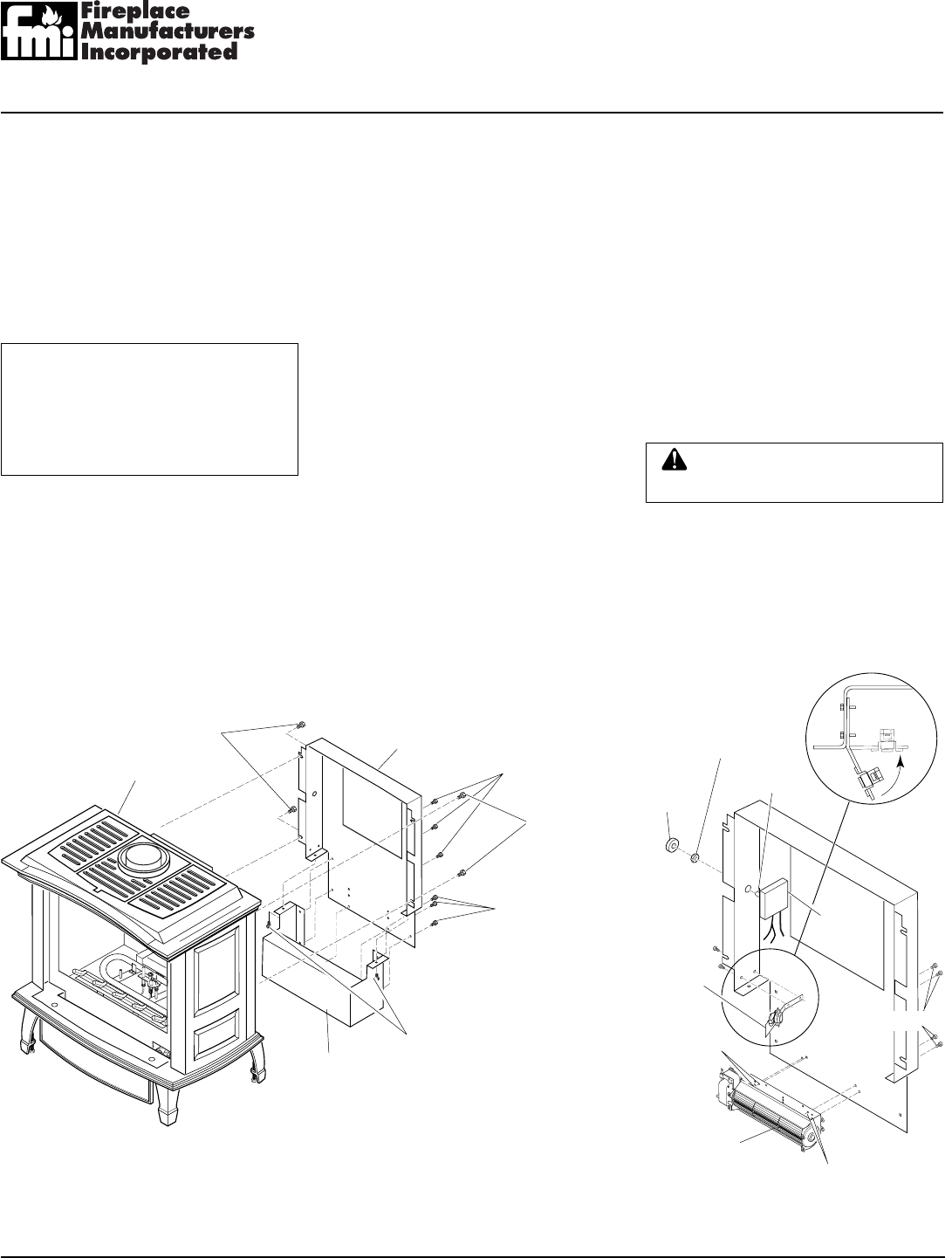
Figure 18 - Removing Rear Cover and Bottom Cover from Stove Body
INSTALLING OPTIONAL
BLOWER ACCESSORY
1. Remove 4 hex bolts securing rear cover
to back of stove body (see Figure 18).
2. Separate bottom cover from rear cover
by loosening the 8 mounting screws
(see Figure 18).
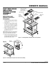
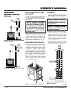
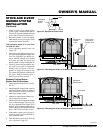
3. Align the holes in the top mounting tabs
of blower with the holes in wall of rear
cover. Using the 4 screws provided,
mount blower and tighten screws se-
curely (see Figure 19).
4. Attach thermal switch and bracket to
inside rear cover wall with two hex head
screws provided as shown. After secur-
ing bracket to rear cover, carefully bend
along existing bend line on bracket to
almost a 90° angle (see Figure 19). This
will allow thermal switch to be posi-
tioned against stove rear wall and sense
temperature when in operating mode.
5. Place speed control on left inside of rear
cover and push the plastic control shaft
through opening (see Figure 19).
6. While supporting speed control, secure
control shaft with lock nut by pushing and
turning lock nut with pliers clockwise
until tight against the side of rear cover.
Place control knob provided onto shaft.
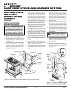
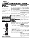
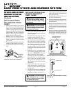
7. Place the green ground wire between the
bottom hole on the blower assembly and
the hex screw and tighten (see Figure 20,
page 9).
8. Connect the blue wire to the blower as-
sembly and one side of the thermal
switch (see Figure 20, page 9).
9. Connect the black wire to the other side
of the thermal switch (see Figure 20,
page 9).
Stove Body
Rear Cover
Bottom Cover
Hex
Bolts
Mounting
Screws
Mounting
Screws
Hex Bolts
Mounting
Screws
Figure 19 - Blower Assembly, Speed
Control, and Thermal Switch Locations
Speed
Control
Blower
Control
Knob
Locknut
Blower
Assembly
Mounting
Holes
Thermal
Switch
and
Bracket
Control
Shaft
TOP VIEW
Mounting
Holes
Screws
10. Connect the white wire to the other ter-
minal on the blower motor assembly
(see Figure 20, page 9). Make sure the
thermal switch has been properly in-
stalled to fit against back of burner sys-
tem after the rear cover assembly has
been reinstalled.
11. Make sure all wire connections to termi-
nals on blower motor and thermal switch
are securely attached and that the screw
retaining the green ground wire is tight.
12. Check to make sure that the power cord
is completely clear of the blower wheel
and that there are no foreign objects in
blower wheel.
13. Peel off the backing paper and stick the
supplied wiring diagram decal on the
inside of rear cover as shown (see Fig-
ure 20, page 9).
14. Connect or reconnect gas supply fol-
lowing instructions in Connecting
Stove and Burner System to Gas Sup-
ply, page 14.