


16
CAST IRON STOVE AND BURNER SYSTEM
107600
For more information, visit www.desatech.com
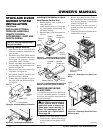
INSTALLING OPTIONAL WALL
MOUNTED THERMOSTAT -
GWMT1, GWMS2
WARNING: Installation must
be done by a qualified installer
familiar with low voltage wiring
procedures.
WARNING: Do not connect
this thermostat to any electrical
source! Electrical shock and/or
fire hazard will occur.
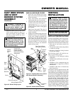
1. Open lower door panel. The valve is
attached to the underside of the burner
system assembly.
2. Disconnect from the valve the wires
running from the ON/OFF switch.
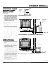
3. Connect one terminal of the wire for
the wall thermostat to the THTP termi-
nal on the valve. Connect remaining
wire terminal to the TH terminal on the
valve. Make sure that the wire termi-
nals are in the positions on the unit as
pictured in Figure 36. If wires are not
connected as shown the thermostat will
not work.
4. Route the wire to a convenient loca-
tion to mount your thermostat (no out-
side wall).
IMPORTANT:
The wire
must not exceed 25 feet in length.
The thermostat should be mounted 54"
above the floor in a location where
there is good air circulation. Avoid
heat sources such as lamps, direct sun-
light, fireplace, or heat and air condi-
tioning ducts.
5. Gently remove the cover of the ther-
mostat from the base. Grasp the sides
of the cover firmly and pull to separate
from the base.
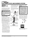
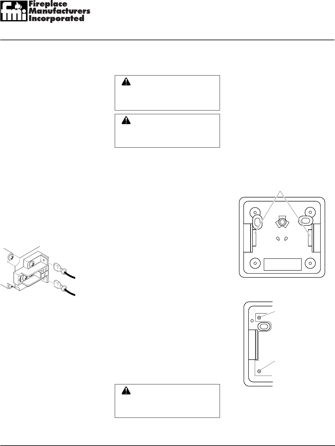
6. Feed the electrical wires through the
rectangular slots (from the back) on
each side of the base (see Figure 37).
WARNING: Do not connect
this thermostat to a power
source. Electrical shock and/or
fire hazard will occur.
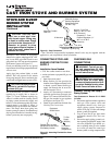
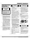
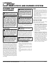
Figure 37 - Back View of Thermostat Base
Feed wires through
rectangular slots
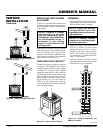
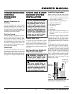
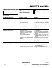
Figure 38 - Thermostat Base Terminal
“W” and “R”
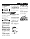
Figure 36 - Control Valve Terminals
W
R
Terminal “W”
Terminal “R”
To Control
Switch or
Optional
Accessory
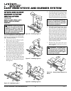
STOVE AND B-VENT
BURNER SYSTEM
INSTALLATION
Continued
INSTALLING OPTIONAL
WALL MOUNTED SWITCH
GWMS2
1. Connect one terminal of 25 ft. wire for
the wall switch to the TPTH terminal
on the valve. Connect remaining wire
terminal to the TH terminal on the valve.
Make sure that the wire terminals are in
the positions on the unit as pictured in
Figure 36. If wires are not connected as
shown, the switch will not work.
2. Route the 25 ft. wire through openings
provided on the sides of the burner sys-
tem to a convenient location to mount
your switch.
3. Connect one bare wire end to each of the
terminals of the GWMS2 wall switch.
4. Install the wall switch and cover in the
wall.
7. Connect one bare wire end to each ter-
minal (“W” and “R”) of the thermostat
base (see Figure 38).
8. Install the base to the wall with screws
provided with thermostat.
9. Move the temperature adjustment back
and forth to insure the bimetal is free
from restrictions.
10. Replace the cover onto the base. (Upon
installation, the thermostat must be al-
lowed to stabilize at room temperature
for a minimum of 30 minutes for proper
operation.)
11. Set the temperature adjustment to the
desired setting. This thermostat has been
electronically calibrated at the factory.
No adjustment or leveling is necessary.