


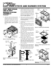
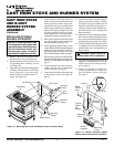
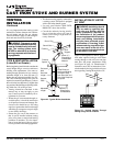
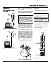
14
CAST IRON STOVE AND BURNER SYSTEM
107600
For more information, visit www.desatech.com
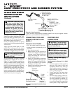
Cap Pipe Nipple Tee Joint
Pressure Testing Gas Supply
Piping System
Test Pressures In Excess Of 1/2 PSIG
(3.5 kPa)
1.
Disconnect appliance with its appliance
main gas valve (control valve) and
equipment shutoff valve from gas
supply piping systems. Pressures in
excess of 1/2 psig (3.5 kPa) will damage
burner system gas regulator.
2. Cap off open end of gas pipe where
equipment shutoff valve was con-
nected.
3. Pressurize supply piping system by ei-
ther opening propane/LP supply tank
valve for propane/LP gas burner sys-
tem or
opening main gas valve located
on or near gas meter for natural gas
burner system,
or using compressed air.
CHECKING GAS
CONNECTIONS
WARNING: Test all gas pip-
ing and connections for leaks
after installing or servicing. Cor-
rect all leaks at once.
WARNING: Never use an open
flame to check for a leak. Apply
commercial leak test solution to all
gas joints. Bubbles forming show
a leak. Correct all leaks at once.
Installation Items Needed
• 5/16" hex socket wrench or nut-driver
• sealant (resistant to propane/LP gas, not
provided)
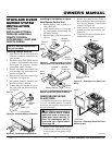
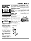
1. Open lower door panel.
2. Route flexible gas line (provided by
installer) from equipment shutoff valve
to burner system. Route flexible gas
supply line through slot in stove bot-
tom and attach to valve.
3. Attach a 45° flare union gas connector
to flexible gas line from gas supply (see
Figure 32). Connect flare union to flex-
ible gas line attached to gas regulator
of fireplace (see Figure 32).
4. Check all gas connections for leaks. See
Checking Gas Connections.
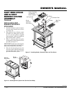
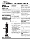
CONNECTING STOVE AND
BURNER SYSTEM TO GAS
SUPPLY
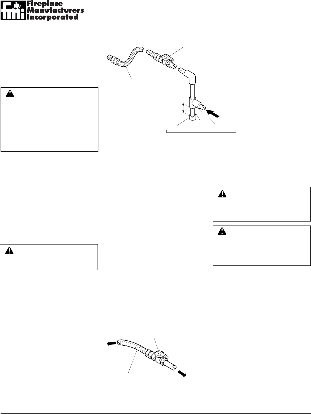
Flexible Gas Line from
Equipment Shutoff Valve
Provided by Installer
Equipment
Shutoff Valve
To Gas
Supply
(Natural)
Figure 32 - Attaching Flexible Gas Lines
Together
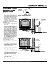
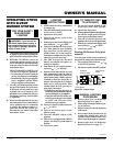
Figure 31 - Gas Connection
* The CSA/AGA design-certified equipment shutoff valve may be supplied with the
appliance or you can purchase it from your dealer.
CSA/AGA Design-
Certified Equipment
Shutoff Valve with
1/8" NPT Tap*
3" Minimum
Propane/LP - From
External Regulator (11"
W.C. to 14" W.C.
Pressure)
Approved Flexible
Gas Line
Sediment Trap/Drip Leg
Natural - From Gas
Meter (5" W.C. to 10.5"
W.C. Pressure )
CAUTION: Use pipe joint seal-
ant that is resistant to liquid pe-
troleum (LP) gas.
We recommend that you install a sediment
trap/drip leg in supply line as shown in
Figure 31. Locate sediment trap/drip leg
where it is within reach for cleaning. Install
in piping system between fuel supply and
heater. Locate sediment trap/drip leg where
trapped matter is not likely to freeze. A
sediment trap traps moisture and contami-
nants. This keeps them from going into
burner system gas controls. If sediment trap/
drip leg is not installed or is installed wrong,
burner system may not run properly.
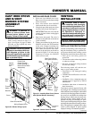
STOVE AND B-VENT
BURNER SYSTEM
INSTALLATION
Continued
CAUTION: Use only new,
black iron or steel pipe. Inter-
nally-tinned copper tubing may
be used in certain areas. Check
your local codes. Use pipe of 1/2"
diameter or greater to allow
proper gas volume to fireplace. If
pipe is too small, undue loss of
pressure will occur.
Installation must include an equipment
shutoff valve, union, and plugged 1/8" NPT
tap. Locate NPT tap within reach for test
gauge hook up. NPT tap must be upstream
from burner system (see Figure 31).
Check your building codes for any special
requirements for locating equipment shutoff
valve to stove.
Apply pipe joint sealant lightly to male
threads. This will prevent excess sealant
from going into pipe. Excess sealant in pipe
could result in clogged burner system valves.
To External
Regulator
(Propane/LP)