


17
107600
OWNER’S MANUAL
For more information, visit www.desatech.com
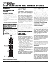
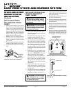
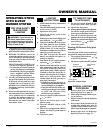
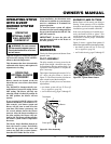
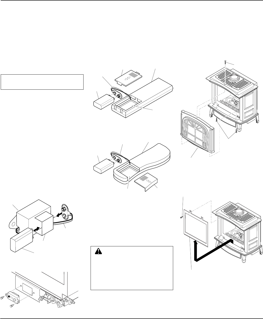
REMOVING/REPLACING
GLASS DOOR
CAUTION: Do not operate this
burner system with a broken
glass door panel or without the
glass door panel securely in
place. For replacement part in-
formation see
Replacement
Parts
, page 26.
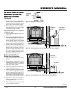
1. Remove 2 bolts from bottom of stove
(if still in place) and one from the top
of stove to remove front panel (see Fig-
ure 43).
You must remove glass door to install logs,
lava rock, and ember material. To remove
glass door, you must first remove the front
panel on stove body.
STOVE AND B-VENT
BURNER SYSTEM
INSTALLATION
Continued
INSTALLING OPTIONAL
WIRELESS HAND-HELD
REMOTE CONTROL
ACCESSORIES - GHRC AND
GHRCTA SERIES
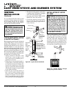
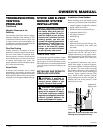
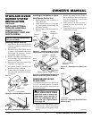
Figure 39 - Installing Battery in Receiver
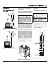
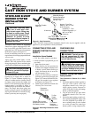
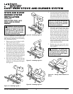
Figure 41 - Installing Battery in Hand-
Held Remote Control Unit (GHRC Series)
Installing 9-Volt Battery in Hand-
Held Remote Control Unit
1. Remove battery cover on back of re-
mote control unit
2. Attach terminal wires to a 9-volt bat-
tery (not included). Place battery into
the battery housing.
3. Replace battery cover onto remote con-
trol unit.
Terminal
Wires
Battery
Cover
9-Volt
Battery
Remote
Control Unit
Battery
Housing
Receiver
Battery Clip
Terminal
Wires
L
O
H
I
P
I
L
O
T
OFF
ON
Figure 40 - Installing Remote Receiver
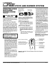
2. Remove the screws from the 2 tabs at
the top of the glass door while holding
door securely keeping it from falling
forward (see Figure 44).
3. Grasp door by both sides and ease it
upward off of the lower bracket (see
Figure 44).
4. To replace glass door, follow the above
instructions in reverse.
Figure 42 - Installing Battery in Hand-Held
Remote Control Unit (GHRCTA Series)
Terminal
Wires
Battery
Cover
9-Volt
Battery
Remote
Control Unit
Battery Housing
Figure 44 - Removing Glass Door from
Burner System
Figure 43 - Removing Front Panel from
Stove
Screw
Glass Door
Bolt
Bolt
Stove Front Panel
Assembly
Continued
NOTICE: Only use alkaline batter-
ies (not included).
Installing Remote Receiver
1. Open bottom door on stove body and
locate the switch plate on the left of the
valve bracket.
2. Disconnect wires from THTP and TH
on control valve that lead to the switch
(see Figure 36, page 16). Discard
switch plate, screws, and nuts.
3. Install 9-volt battery (not included) into
receiver battery clip and connect to ter-
minals (see Figure 39).
4. Place receiver into valve bracket and
align holes (see Figure 40).
5. Use push-in fasteners included with
receiver to secure to bracket.
6. Connect the wires from the receiver to
the valve at TH and THTP (see Figure
36, page 16).
9-Volt Battery