


108117-01J
For more information, visit www.desatech.com
For more information, visit www.desatech.com
18
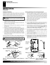
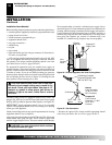
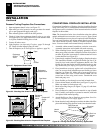
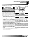
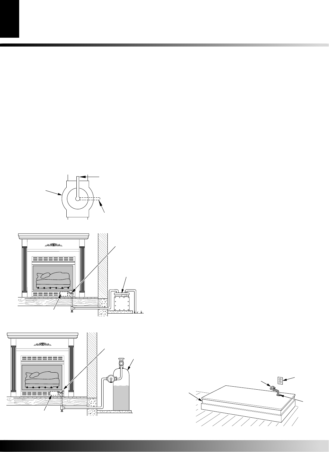
Figure 28 - Checking Gas Joints for Natural Gas Fireplace
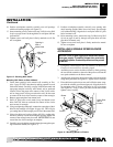
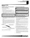
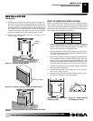
Figure 29 - Checking Gas Joints for Propane/LP Gas Fireplace
INSTALLATION
Checking Gas Connections (Cont.)
Conventional Fireplace Installation
INSTALLATION
Continued
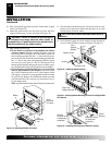
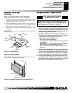
CONVENTIONAL FIREPLACE INSTALLATION
Conventional installation of fireplace involves installing fireplace
along with corner, face, or cabinet mantel with hearth base accesso-
ries against a wall in your home. Follow instructions below to install
fireplace in this manner.
Note:
The instructions below show installation using the cabinet
mantel and hearth base accessories (see Accessories, pages 36 and
37. The hearth base accessory shown is optional for this installation.
You can install fireplace and cabinet mantel directly on the floor.
The corner mantel accessory cannot be installed with the hearth
bases. You must install corner mantel directly on the floor.
1. Assemble cabinet mantel, hearth base, and trim accessories.
Assembly instructions are included with each accessory.
2. When installing blower, install a properly grounded, 120 volt
three-prong electrical outlet at fireplace location if an outlet is
not there. If possible, locate outlet so cabinet mantel will cover
it when installed (see Figure 30).
3. If not already completed, install gas piping to fireplace location.
This installation includes an approved flexible gas line (if al-
lowed by local codes) after the equipment shutoff valve. The
flexible gas line must be the last item installed on the gas pip-
ing. See Installing Gas Piping to Fireplace Location, page 14.
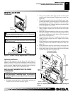
4. Place hearth base accessory against wall at installation loca-
tion. Cut an access hole in hearth top to run flexible gas line to
fireplace (see Figure 30). Make sure to locate access hole so
cabinet mantel will cover it when installed.
Note:
You can
secure base to floor using wood screws. Countersink screw
heads and putty over.
5. Route flexible gas line through access hole in hearth base.
6. Center cabinet mantel on hearth base (see Figure 31, page 19).
Make sure mantel is flush against wall.
7. Break off nailing flanges (see Figure 32, page 19) with ham-
mer or pliers.
8. Place cardboard or other protective material on top of hearth
base. Carefully set fireplace on protective material, with back
of fireplace inside mantel opening.
9. Attach flexible gas line to fireplace gas regulator. See Con-
necting Fireplace to Gas Supply, page 17.
10. Route electrical cord(s) through access holes in either side of fire-
place with bushing. Plug electrical cord(s) into electrical outlet.
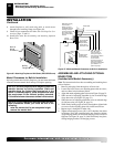
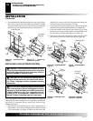
Figure 30 - Placing Hearth Base Accessory Against Wall
Electrical
Outlet
Hearth
Base
Rigid Pipe and
Gas Shutoff Valve
Gas Line
Access
Hole
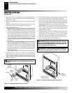
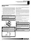
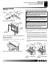
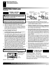
Figure 27 - Equipment Shutoff Valve
Pressure Testing Fireplace Gas Connections
1. Open equipment shutoff valve (see Figure 27).
2. Open main gas valve located on or near gas meter for natural
gas or open propane/LP supply tank valve.
3. Place manual ignition switch in the OFF position.
4. Check all joints from equipment shutoff valve to gas valve
(see Figure 28 or 29). Apply noncorrosive leak detection fluid
to all joints. Bubbles forming show a leak.
5. Correct all leaks at once.
6. Light fireplace (see Operating Fireplace, pages 23 through
25). Check all other internal joints for leaks.
7. Turn off fireplace (see To Turn Off Gas to Appliance, page 24).
ON
POSITION
OFF
POSITION
Open
Closed
Equipment
Shutoff
Valve
Equipment
Shutoff Valve
Manual Gas Valve
Gas Meter
Equipment
Shutoff
Valve
Manual Gas Valve
Propane/LP
Supply
Tank