


108117-01J
For more information, visit www.desatech.com
For more information, visit www.desatech.com
21
21
INSTALLATION
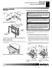
Assembling And Attaching Optional Brass Trim (Cont.)
Installing Hood
Installing Logs (CGEFP33PR/CGEFP33NR)
INSTALLATION
Continued
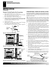
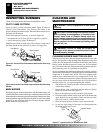
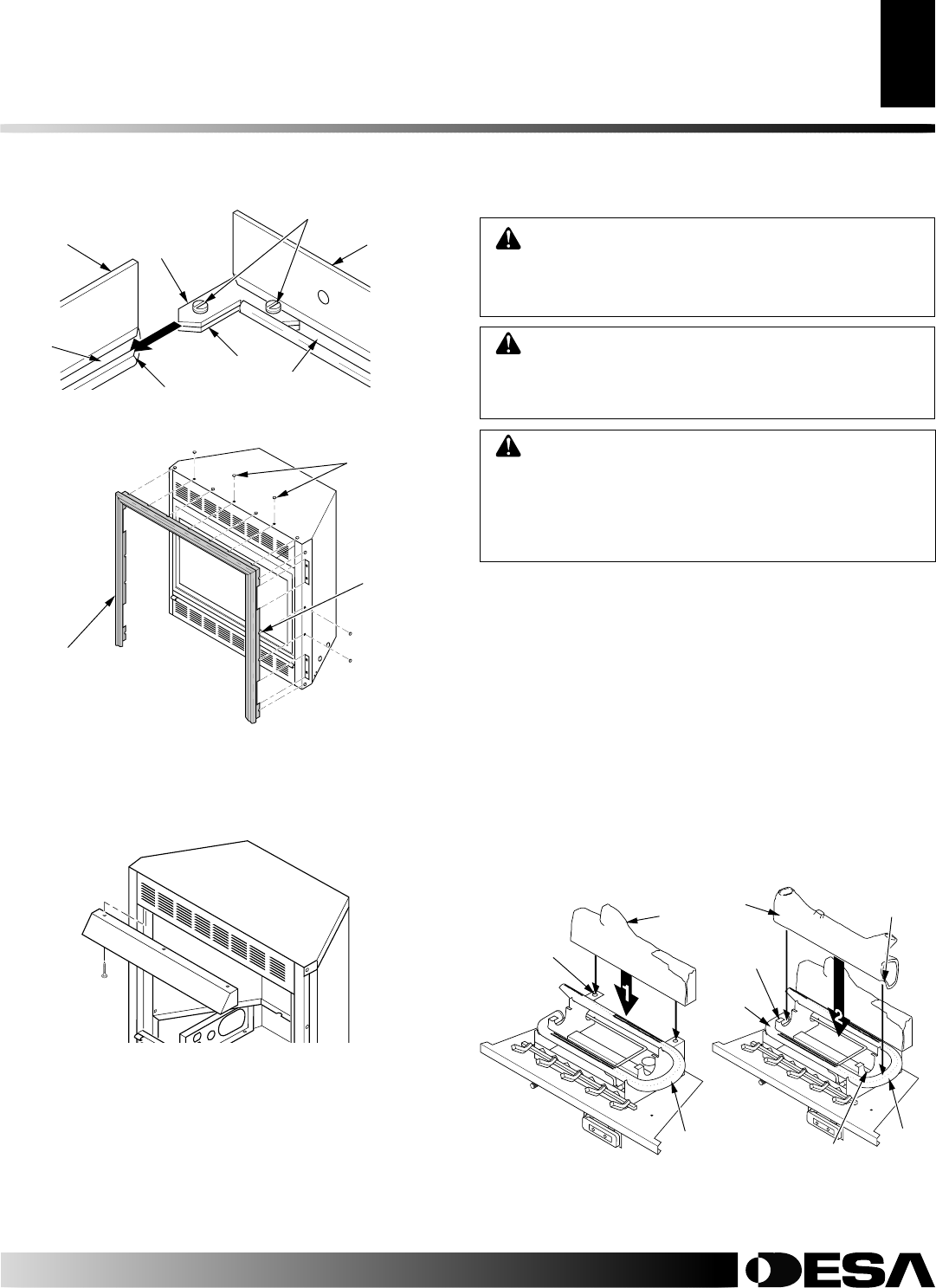
Figure 39 - Attaching Brass Trim to Fireplace (EFP33PR Shown)
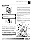
Trim
Hanging
Screws
Assembled
Brass Trim
Hanging
Notches
on Trim
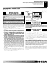
Figure 38 - Assembling Brass Trim
Slot
Mitered Edge
Slot
Shim
Set Screws
Adjusting
Plate
Side Brass
Trim
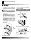
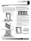
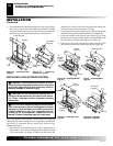
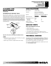
Figure 40 - Installing Hood to Firebox (EFP33PR Shown)
INSTALLING HOOD
Install hood to top of firebox as shown in Figure 40. Use 3 Phillips
screws provided.
Top Brass
Trim
WARNING: Failure to position the parts in accor-
dance with these diagrams or failure to use only parts
specifically approved with this heater may result in
property damage or personal injury.
CAUTION: Do not remove the warning and in-
struction labels attached to the heater base assem-
bly. These markings contain important warranty in-
formation.
CAUTION: After installation and periodically there-
after, check to ensure that no flame comes in contact
with any log. With the heater set to HI, check to see if
flames contact any log. If so, reposition logs accord-
ing to the log installation instructions in this manual.
Flames contacting logs will create soot.
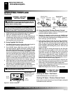
INSTALLING LOGS (CGEFP33PR/CGEFP33NR)
Each log is marked with a number. These numbers will help you
identify the log when installing. It is very important to install these
logs exactly as instructed. Do not modify logs. Only use logs
supplied with heater.
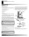
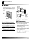
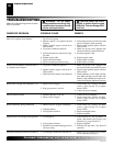
1. Locate pegs on the bottom of back log (#1). Slide these pegs into
the holes in the grate base behind the burner (see Figure 41).
2. Place the base of the middle log (#2) in the U-shaped slots of
the grate base in front of the back log. The cutout on the right
of the middle log should fit over the burner (see Figure 42).
Make sure the front of the middle log is resting on the tabs of
the grate base and the cutout area is centered over the burner
“U” bend.
3. Locate the recesses on the back of the front log (#3). Fit these
recesses between the posts of the grate base (see Figure 43,
page 22).
Figure 41 - Installing Back
Log (#1)
Figure 42 - Installing Middle
Log (#2)
Hole in
Grate
Base
Back
Log
(#1)
Burner
Burner
Tab
Middle
Log
(#2)
Cutout
U-Shaped Slot
“U” Bend