


12
107553
UNVENTED NATURAL GAS LOG HEATER
For more information, visit www.desatech.com
INSTALLATION
Continued
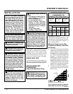
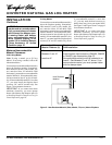
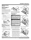
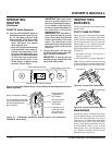
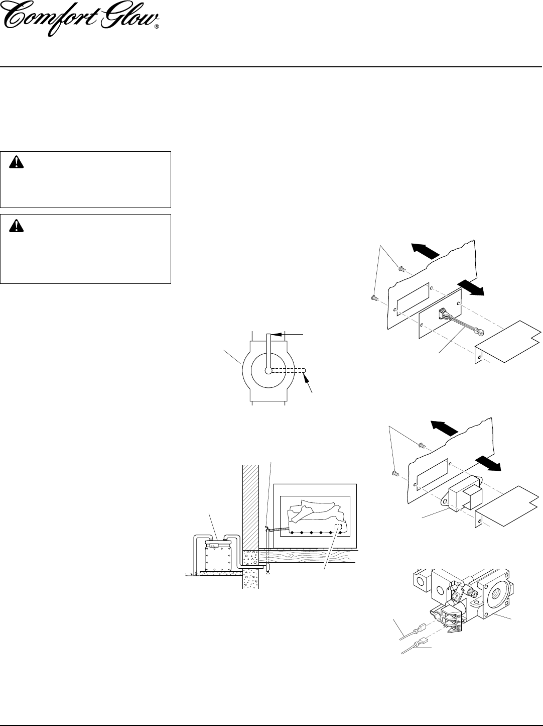
Figure 14 - Equipment Shutoff Valve
ON
POSITION
OFF
POSITION
Open
Equipment
Shutoff Valve
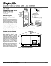
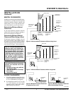
Figure 15 - Checking Gas Joints
Gas Meter
Equipment
Shutoff Valve
Thermostat Gas
Valve or Control
Valve Location
Closed
WARNING: Never use an open
flame to check for a leak. Apply a
noncorrosive leak detection fluid
to all joints. Bubbles forming show
a leak. Correct all leaks at once.
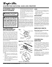
WARNING: Test all gas pip-
ing and connections for leaks
after installing or servicing. Cor-
rect all leaks at once.
CHECKING GAS
CONNECTIONS
Pressure Testing gas Supply
Piping system
Test Pressures In Excess Of 1/2 PSIG
(3.5 kPa)
1. Disconnect appliance with its appliance
main gas valve (control valve) and equip-
ment shutoff valve from gas supply pip-
ing system. Pressures in excess of 1/2
psig will damage heater regulator.
2. Cap off open end of gas pipe where
equipment shutoff valve was connected.
3. Pressurize supply piping system by either
using compressed air or opening main gas
valve located on or near gas meter.
4. Check all joints of gas supply piping
system. Apply noncorrosive leak detec-
tion fluid to gas joints. Bubbles form-
ing show a leak.
5. Correct all leaks at once.
6. Reconnect heater and equipment
shutoff valve to gas supply. Check re-
connected fittings for leaks.
Test Pressures Equal To or Less Than
1/2 PSIG (3.5 kPa)
1. Close equipment shutoff valve (see
Figure 14).
2. Pressurize supply piping system by either
using compressed air or opening main gas
valve located on or near gas meter.
3. Check all joints from gas meter to equip-
ment shutoff valve (see Figure 15). Ap-
ply noncorrosive leak detection fluid to
gas joints. Bubbles forming show a leak.
4. Correct all leaks at once.
Pressure Testing Heater Gas
Connections
1. Open equipment shutoff valve (see
Figure 14).
2. Open main gas valve located on or near
gas meter.
3. Make sure control knob of heater is in
the OFF position.
4. Check all joints from equipment
shutoff valve to control valve (see Fig-
ure 15). Apply noncorrosive leak de-
tection fluid to gas joints. Bubbles
forming show a leak.
5. Correct all leaks at once.
6. Light heater (see Operating Heater,
pages 15 through 17). Check all other
internal joints for leaks.
7. Turn off heater (see To Turn Off Gas to
Appliance, page 16).
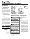
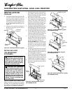
Front
Back
Front
Back
INSTALLING REMOTE
RECEIVER UNIT
1. Disconnect switch wires from the con-
trol valve.
2. Remove phillips head screws and
heat shield.
3. Remove switch plate (see Figure 16).
Discard after removing.
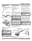
4. Install remote receiver unit onto gas log
heater base using phillips head screws.
5. Connect wires as shown in Figure 18.
Figure 16 - Switch Plate and Wiring Har-
ness (Switch Plate and Orientation May
Vary Depending On Model)
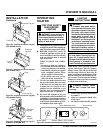
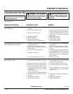
Figure 17 - Installing Remote Receiver
Wires
Screws
Remote
Receiver
Screws
Figure 18 - Connecting Wires
Valve
White
Wire From
Receiver
Red Wire From Receiver