


111916-01D
For more information, visit www.desatech.com
For more information, visit www.desatech.com
9
9
INSTALLATION
Continued
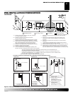
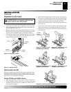
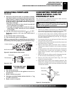
REMOVING GLASS PANEL
CAUTION: Before you proceed, make sure your
gas control valve is in the OFF position.
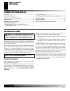
1. To remove louvers, pull both spring latches (located in each
end of louver) toward center of appliance at the same time
until disengaged from locating holes. Repeat for bottom end
spring latches (see Figure 16).
2. Remove screen rod by removing rod loop from glass door center
bracket. Slide screen rod either to the left or right of fireplace until
one end is free to completely remove screen from fireplace.
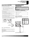
3. Undo latches located on top and bottom of firebox (see Figure
17). Carefully swing door to the left. The glass door is se-
curely mounted to the firebox with 5 screws.
Figure 16 - Removing Louvers
Figure 17 - Spring Latches
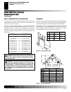
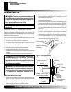
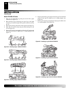
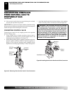
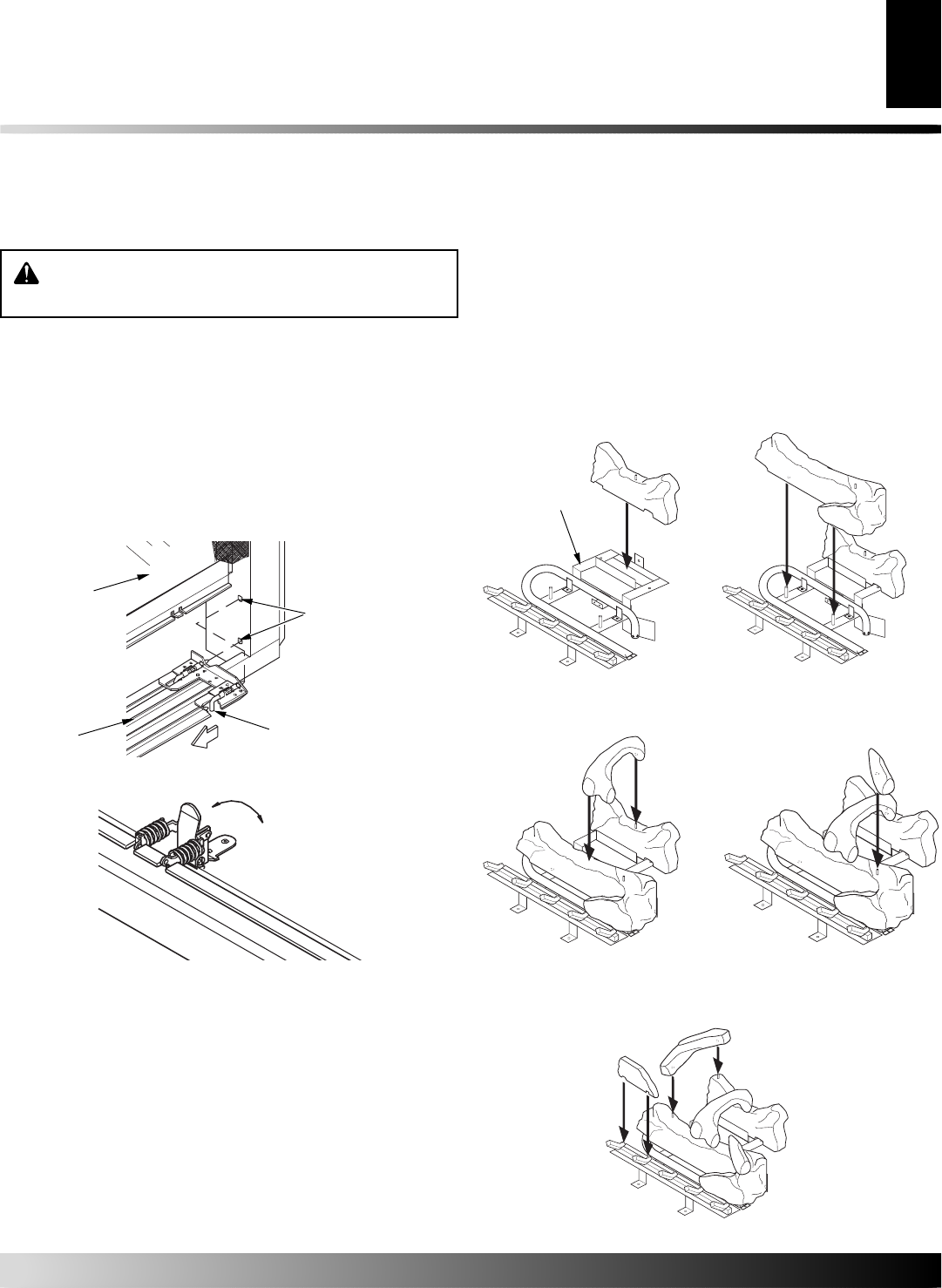
INSTALLING LOG SET
Each log is marked with a number in the following diagram. These
numbers will help in identifying the logs when installed. It is very
important to install these logs exactly as instructed. Do not modify
logs. Only use logs supplied with fireplace.
Models CD32M and CD36M-A Series
1. Place log #1 (back log) on top of grate as shown in Figure 18
for the CD36M-A Series. Log #1 will go in front of the metal
partition on grate (see Figure 18). Make sure notches in bot-
tom of log fit over grate.
Figure 18 - Installing Log #1
(CD36M-A Series Shown)
Figure 19 - Installing Log #2
(CD36M-A Series Shown)
Glass
Locating
Holes
Spring
Latch
Bottom
Louver
Open
Close
1
2
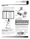
2. Place log #2 (large front log) over pins on grate (see Figure 19).
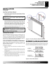
3. Place log #3 (c-shaped crossover log) onto rear and front logs
as shown in Figure 20. Make sure it is seated properly on the
smooth surface on front log and on the pin on back log.
4. Place log #4 (small round log) on pin on right side of front log
(see Figure 21).
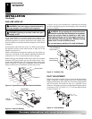
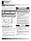
5. Place log #5 (small front log) onto the front left part of grate
making sure notches fit over prongs of grate (see Figure 22).
6. Place log #6 onto two pins on left side of back and front logs
(see Figure 22).
3
Figure 20 - Installing Log #3
(CD36M-A Series Shown)
4
Figure 21 - Installing Log #4
(CD36M-A Series Shown)
5
6
Figure 22 - Installing Logs #5 and #6 (CD36M-A Series Shown)
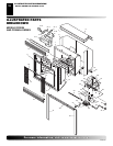
INSTALLATION
Removing Glass Panel
Installin Log Set
CD32M
Log #1
Placement