


111916-01D
For more information, visit www.desatech.com
For more information, visit www.desatech.com
6
VENTING INSTALLATION
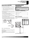
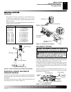
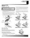
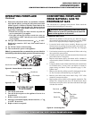
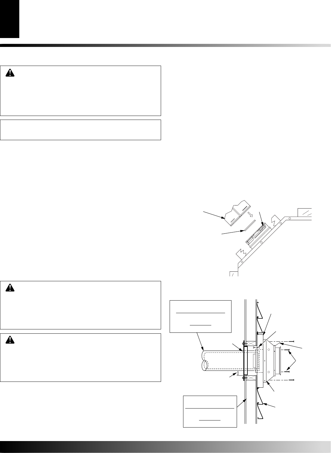
1. Install elbow to fireplace collar adapter located on back of the
unit at a 45° angle. Slide elbow over collar and twist to lock.
Check to insure proper connection (see Figure 6).
2. Continue to install remainder of pipe for desired installation.
Make sure each section is twist-locked securely.
Figure 6 - Venting Installation
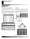
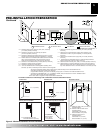
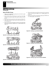
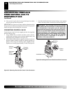
Figure 7 - Vent Termination (Horizontal)
Direct-Vent Pipe
CD32M and CD36M-A
4
1
/4" Inner and 7
1
/4" Outer
CD42M-A
5" Inner and 8" Outer
Wall
Firestop
Maintain 1" Minimum Air
Space Around Outer Pipe
when Penetrating a Wall
Horizontal
Termination
(Vent Cap)
Screws
Exterior Wall with
Vinyl Siding
Deflector
Shield
Minimum Pipe
Overlap 1
1
/4"
Siding Standoff
(Optional)
Framed Openings
CD32M and CD36M-A
10" x 10"
CD42M-A
10
3
/4" x 10
3
/4"
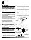
WARNING: Read all instructions completely and
thoroughly before attempting installation. Failure to
do so could result in serious injury, property damage
or loss of life. Operation of improperly installed and
maintained venting system could result in serious
injury, property damage or loss of life.
NOTICE: Failure to follow these instructions will void
the warranty.
INSTALLATION
Female Locking Lugs
Vertical Flue Restrictor
(For Vertical Venting
Application)
Male Locking
Lugs
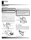
3. When installation of vent pipe is complete, in stall vent termi-
nation. Depending on the location of your fireplace, you will
vent vertically or horizontally.
4. Allow 1" of pipe to protrude from internal wall, depending on
wall thickness. See Figure 7.
5. For horizontal installation, an optional siding standoff may be
installed between the vent cap and the exterior wall. Secure
horizontal vent cap to standoff. Secure standoff/vent cap as-
sembly to wall (see Figure 7). Do not seal termination to vent
pipe. The vent termination must be removable for service pipe
inspection.
6. For vertical installation, a vertical termination is available. Also
for vertical venting application, install vertical flue restrictor
into inner collar of fireplace as shown in Figure 6.
When installing a length of pipe for vertical termination that is
over 3 ft., support the pipe every 3 ft. using metal wall straps.
Vertical to horizontal pipe must be kept at a 1 ft. to 4 ft. ratio
with a maximum run of no more than 20 ft.
VENTING INSTALLATION PRECAUTIONS
Consult local building codes before beginning the installation. The
installer must make sure to select the proper vent system for installa-
tion. Before installing vent kit, the installer must read this fireplace
manual and vent kit instructions.
Only a qualified service person should install venting system. The
installer must follow these safety rules:
• Wear gloves and safety glasses for protection
• Use extreme caution when using ladders or when on roof tops
• Be aware of electrical wiring locations in walls and ceilings
The following actions will void the warranty on your venting system:
• Installation of any damaged venting component
• Unauthorized modification of the venting system
• Installation of any component part not manufactured or approved
by DESA
• Installation other than as instructed by these instructions
WARNING: Horizontal sections of this vent sys-
tem require a minimum clearance of 2" from the top
of the pipe and 1" minimum to the sides and bottom.
Vertical sections of this system require a minimum
of 1" clearance to combustible materials on all
sides of the pipe.
WARNING: This gas fireplace and vent assembly
must be vented directly to the outside. The venting
system must NEVER be attached to a chimney serv-
ing a separate solid fuel burning appliance. Each gas
appliance must use a separate vent system. Do not
use common vent systems.
INSTALLATION
Venting Installation Precautions
Venting Installation