


111916-01D
For more information, visit www.desatech.com
For more information, visit www.desatech.com
8
INSTALLATION
Continued
GAS LINE HOOK-UP
WARNING: Gas line hook-up should be done by
your gas supplier or a qualified service person.
WARNING: Before you proceed, make sure your
gas supply is OFF.
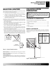
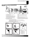
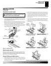
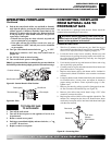
An equipment shutoff valve has been included in the fireplace's gas
supply system. However, consider installing an extra shutoff valve
outside the appliance’s enclosure (check local codes), where it can
be accessed more conveniently with a key through a wall as shown
in Figure 12.
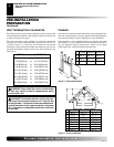
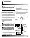
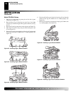
In conformance with local codes, route a 1/2" NPT gas line towards
the appliance coming in from either the left or right side of the
fireplace (see Figure 13).
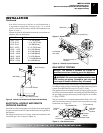
Install a sediment trap between the incoming gas line and the gas
control box. (see Figure 14). The sediment trap should extend down
a minimum of 3" (7.62 cm) beyond the center of the pipe.
When routing gas line through conduit sleeve, make sure to repack
insulation to fill gaps between gas line and conduit sleeve. Com-
pounds used on threaded joints of gas piping shall be resistant to the
action of propane or natural gas. Compounds should be applied
lightly to ensure excess sealant does not enter the gas line.
WARNING: All gas piping and connections must
be tested for leaks after the installation is completed.
Never use an open flame to check for a leak. After
ensuring that the gas valve is open apply commercial
leak detection fluid to all gas joints. Bubbles forming
show a leak. Correct all leaks at once.
Do not operate any appliance if a leak is detected.
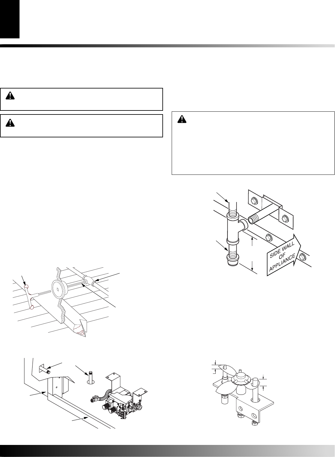
Figure 12- Typical Exterior Wall Gas Shutoff Installation
Key
Extension
Shutoff Valve
Figure 13 - Gas Line Routing
Figure 14 - Sediment Trap
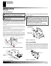
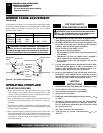
PILOT ADJUSTMENT
The pilot or electrode assembly is factory preset for the proper flame
height. Alterations to these settings may have occurred during
shipping and handling. If this is the case, some minor readjustments
may be necessary and should be done by a qualified service
technician. The proper settings for the thermopile height should be
at a distance of 3/8" (.95 cm) to 1/2" (1.27 cm) from the pilot flame
as shown in Figure 15.
Figure 15 - Pilot Assembly
3" Min.
Sediment Trap
(Not Supplied)
Incoming 1/2" Gas
Line Permitted By
Local Codes
3" Min.
(7.6 cm)
1/8"
(0.3cm)
3/8" - 1/2"
(.95cm-1.3cm)
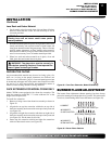
Complete your gas line installation by connecting the incoming
gas line to the flexible gas line. Secure tightly with a wrench but
do not over-tighten.
T
I
P
OFF
T
O
L
ON
P
I
L
O
TPTH
TP
TH
Gas Routing
(Right Side Not Shown)
Side of
Fireplace
Front Face
INSTALLATION
Gas Line Hook-Up
Pilot Adjustment