


111916-01D
For more information, visit www.desatech.com
For more information, visit www.desatech.com
7
7
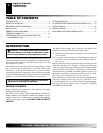
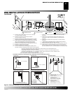
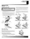
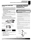
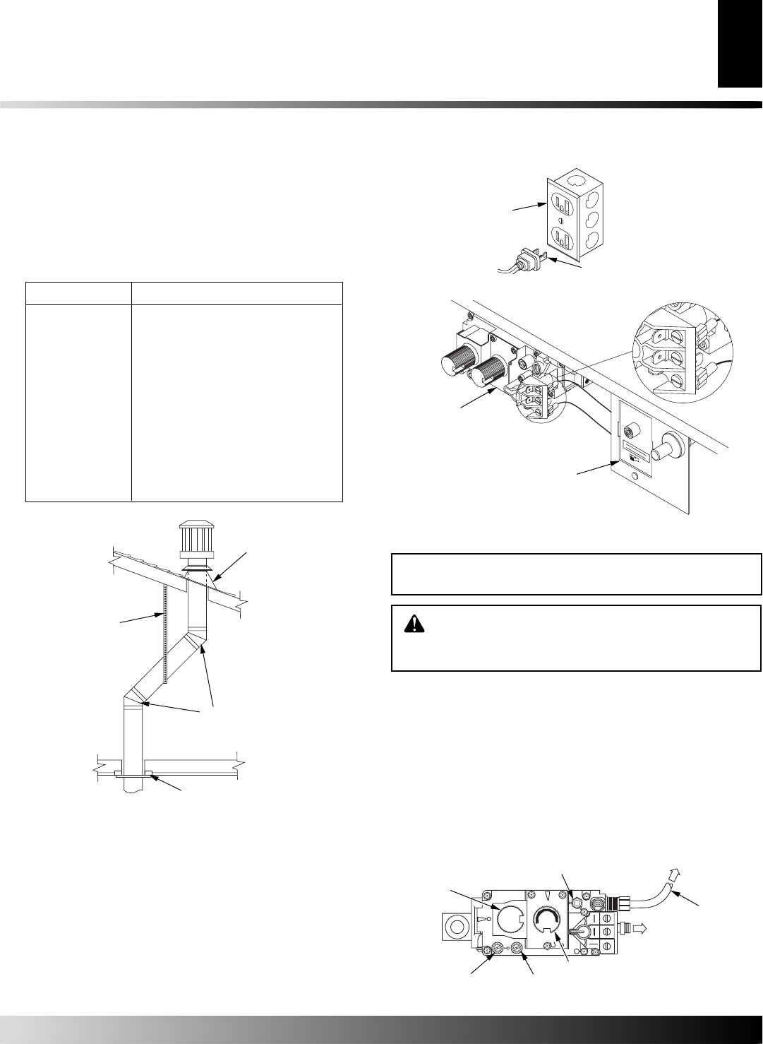
Figure 8 - Vertical Termination with Offset and Wall Strap
Wall Strap
Roof Flashing
45° Elbows
Ceiling Firestop
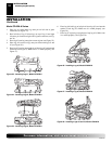
Roof Pitch Minimum Height Above Roof
Flat - 7/12 1 ft. (30.48 cm)
7/12 - 8/12 1
1
/2 ft. (45.72 cm)
8/12 - 9/12 2 ft (60.96 cm)
9/12 - 10/12 2
1
/2 ft (76.20 cm)
10/12 - 11/12 4 ft (121.92 cm)
11/12 - 14/12 5 ft (152.40 cm)
14/12 - 16/12 6 ft (182.88 cm)
16/12 - 18/12 7 ft (213.36 cm)
18/12 - 20/12 7
1
/2 ft (228.60 cm)
20/12 - 21/12 8 ft (243.84 cm)
INSTALLATION
Continued
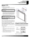
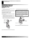
ELECTRICAL HOOKUP AND REMOTE
RECEIVER DIAGRAM
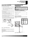
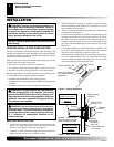
An outlet box with two receptacles (see Figure 9) has been supplied
for your convenience and is located inside on the lower right side of
the fireplace.
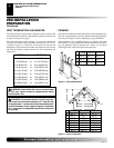
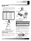
The remote control receiver is factory wired and connected to the
convertible gas valve as shown in Figure 10.
Figure 9 - Duplex Outlet
Three-prong Plug
GAS SUPPLY TESTING
NOTICE: This section is intended as a guide for
qualified technicians installing gas to the appliance.
WARNING: Do not connect appliance before pres-
sure testing gas piping. Damage to gas valve may
result and an unsafe condition may be created.
The appliance and its individual shutoff valve must be disconnected
from the gas supply piping system during any pressure testing of that
system at test pressures in excess of 1/2 psig (3.5 kPa).
The appliance must be isolated from the gas supply piping system
by closing its individual shutoff valve during any pressure testing of
the gas supply piping system at test pressures equal to or less than
1/2 psig (3.5 kPa).
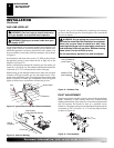
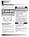
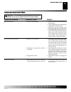
The gas control valve is secured underneath the firebox. Two 1/8"
ports are provided on the gas control valve for pressure test gauge
connections (see Figure 11).
Figure 10 - Remote Control Receiver
Figure 11 - Gas Control Valve
O
F
F
P
I
L
O
T
O
N
L
O
H
I
P
I
L
O
T
EA
16AI
7
TPTH TP TH
ON/OFF
Knob
Pilot Adjustment
Inlet
Pressure
Outlet Pressure
Flame Adjustment Knob
Pilot Gas
Line Do
Not Kink
To Pilot Burner
To Main
Burner
Outlet Box
OFF
TH
TP
TPTH
REMOTE OFF ON
ON
T
P
I
L
O
O
T
L
I
P
TPTH
TP
TH
Remote Control
Receiver
Convertible
Gas Valve
If an offset is necessary in the attic to avoid obstruction, it
is important to support the vent pipe every 3 ft. to avoid
excessive stress on the elbows and possible separation (see
Figure 8, page 7).
Clearances must be maintained between the roof and the ter-
mination. Refer to chart below.
INSTALLATION
Venting Installation (Con.)
Electrical Gookup and Remote Reeiver Diagram
Gas Supply Testing