


- 3 - For more information, visit www.desatech.com
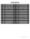
STEP 3: Set the fireplace directly in front of this opening and
slide the unit back until the nailing flanges touch the side
framing.
STEP 4: Check the level of the fireplace and shim with sheet
metal if necessary. Make sure the unit is balanced on each
side.
STEP 5: Before securing fireplace to prepared framing, the
ember protector (provided), must be placed between the hearth
extension (not supplied), and under the bottom front edge of
the fireplace to protect against glowing embers falling
through. If the fireplace is to be installed on a raised platform,
a Z-type ember protector (not supplied) must be fabricated to
fit your required platform height. The ember protector should
extend under the fireplace a minimum of 1 - 1/2”. The ember
protector should be made of galvanized sheet metal (28-gage
minimum).
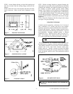
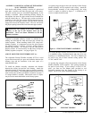
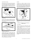
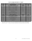
STEP 6: Secure the fireplace to the floor using tie-down straps
(see figure 3) to prevent shifting.
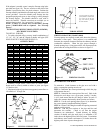
HEARTH EXTENSION
A hearth extension projecting a minimum of 16” in front of
and a minimum of 8” beyond each side of the fireplace
opening is required to protect combustible floor construction
in front of the fireplace. Fabricate a hearth extension using a
material which meets the following specifications: a layer of
non-combustible, inorganic material having a thermal
conductivity of K = 0.84 BTU IN/FT. HR. F (or less) at 1”
thick. For example, if the material selected has a K factor of
0.25, such as glass fiber, the following formula would apply:
Thermal conductivity “K” of materials can be obtained from
the manufacturer or supplier of the non-combustible material.
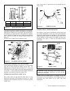
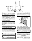
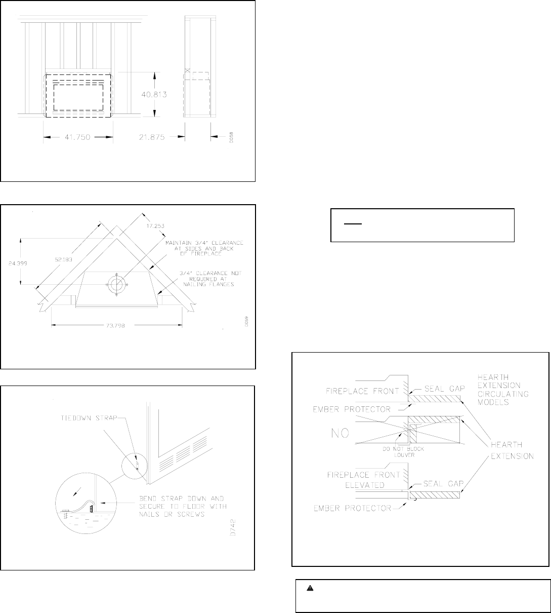
If the hearth extension is to be covered, use non-combustible
material such as tile, slate, brick, concrete, metal, glass,
marble, stone etc. Provide a means to prevent the hearth
extension from shifting and seal gap between the fireplace
frame and hearth extension with a non-combustible material
(see figure 4).
WARNING: Hearth extension is to be installed onl
y
as illustrated.
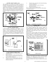
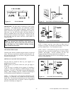
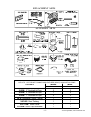
Figure 2 CORNER INSTALLATION
0.25 x 1.0” = 0.30 thickness required
0.84
Figure 1 FRAMING DIMENSION
Figure 4 HEARTH EXTENSION
Figure 3 TIE-DOWN STRAP