


-5 - For more information, visit www.desatech.com
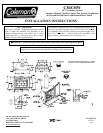
ASSEMBLY AND INSTALLATION OF THE DOUBLE
WALL CHIMNEY SYSTEM
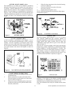
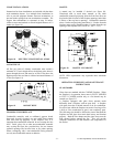
Each double wall chimney section is consist of a galvanized
outer pipe, a stainless steel inner flue pipe and a wire spacer.
The pipe sections must be assembled independently as the
chimney is installed. When connecting chimney directly to
the fireplace, the inner flue pipe section must be installed first
with the lanced side up. The outer pipe section can then be
installed over the flue pipe section with the hemmed end up.
Press down on each pipe section until the lances securely
engage the hem on the fireplace starter. The wire will assure
the proper spacing between the inner and outer pipe sections.
Continue to assemble chimney sections as outlined above,
making sure that both the inner and outer pipe sections are
locked together. When installing double wall “snap lock”
chimney together, it is important to assure the joint between
the chimney sections is locked. Check by pulling chimney
upward after locking. The chimney will not come apart if
properly locked. It is not necessary to add screws to keep the
chimney together (exception – see page 6 figure 12).
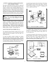
ADJUSTABLE FIRESTOP THIMBLE (FST-A):
The Adjustable Firestop Thimble Assembly (FST-A) is used
to provide the necessary air space and clearance between the
chimney pipe and the insulation in the attic space of a
manufactured home.
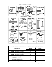
To install the thimble assembly, determine the distance
between the ceiling joist and the roof framing. Attach the
adjustable thimble to the firestop spacer so that the assembly
will cover the distance. The adjustable thimble should be even
with or above the roofline (see thimble extensions on page 12
if a longer thimble is needed). Sheet metal screws or staples
may be used to attach the thimble to the firestop spacer.
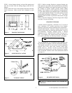
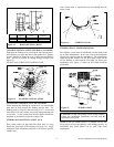
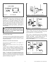
An opening large enough to allow the insertion of the firestop
thimble assembly will be required in the ceiling. Attach the
firestop/thimble assembly to the ceiling/ceiling joist using
screws or staples as shown in figure 8. A minimum of 8
screws or staples should be used.
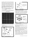
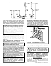
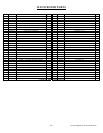
The firestop thimble assembly should also be used where there
is a cathedral ceiling, insulation barrier and roof, all in one
assembly in a manufactured home. The FST-A Thimble can
be used in any one of three common ceiling pitches: flat,
12”/96”, and 30”/144”.
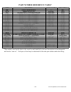
An opening big enough to allow the insertion of the firestop
thimble assembly will be required. This opening depends on
the pitch of your ceiling. If your ceiling is a flat or 12”/96”
pitch, you must use the adapter plate provided to seal
unwanted openings since the opening in the firestop is an
ellipse. For 30”/144” pitch, discard the adapter.
Figure 8 FIRESTOP THIMBLE
Figure 9 FIRESTOP THIMBLE ASSEMBLY
Figure 10 FIRESTOP THIMBLE
WARNING: The opening in the collar around the
chimne
y
at the top of the fireplace must not be
obstructed. Never use blown insulation to fill the
chimney enclosure.