


- 6 - For more information, visit www.desatech.com
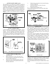
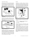
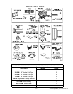
If the adapter is needed, secure it onto the firestop using holes
provided (see figure 10). The row of holes on the sides of the
thimble is provided to allow for pitch variances. Position the
firestop assembly and thimble to desired angle and secure with
screws provided. Insert the thimble and firestop into the
prepared opening and secure to the ceiling by nailing through
the firestop flanges. The thimble should be even with or
above the roofline. Thimble extensions are available (as an
option) when required. See “accessories” on page 12.
NOTE: If there is a second story in the home, firestop
spacer V3600FS-8DM will be required. See “Firestop
Spacer”.
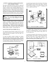
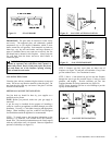
INSTRUCTIONS WHEN ELBOW OFFSET (30E-8DM)
OF CHIMNEY IS NEEDED
TO INSTALL ELBOWS
1. To achieve desired offset, you may install combinations of
12”, 18”, 24”, 36” and 48” length of double wall pipe (SEE
SINGLE OFFSET CHARTAND FIGURE 12).
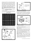
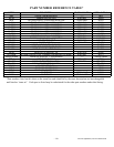
OFFSET CHART
2. Chimney weight above offset rests on return elbow.
Straps must be securely nailed to rafters or joists (see figure
12, details a & b).
3. Maximum length of pipe between supports (return elbow or
12S-8DM) is 2’ of angle run.
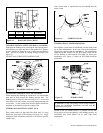
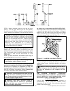
FIRESTOP SPACERS (V3600FS-8DM)
Firestop spacers are required at each point where the chimney
penetrates a floor space. Their purpose is to establish and
maintain the required clearance between the chimney and the
combustible materials. When the pipe passes through a
framed opening into a living space above, the firestop must be
placed onto the ceiling from below as shown in figure 13.
PENETRATING THE ROOF
To maintain a 1-inch clearance to the pipe on a roof with a
pitch, a rectangular opening must be cut.
STEP 1: Determine the center point through which the pipe
will penetrate the roof.
STEP 2: Determine the center point of the roof. Pitch is the
distance the roof drops over a given span, usually 12 inches.
A 6/12 pitch means that the roof drops 6 inches for each 12
inches one measure horizontally down from the roof rafters.
STEP 3: Use the roof opening chart (figure 14) to determine
the correct opening length and flashing required.
STEP 4: Remove the shingles around the opening measured
and cut out this section.
STEP 5: Add the next sections of the pipe until the end
penetrates the roofline. Check to see that the proper
clearances are maintained. Extend chimney by adding
sections of double wall pipe until pipe is a minimum of 30
inches above the highest point of the roof cutout. Termination
and chimney must extend a minimum of 36 inches above the
highest point where it passes through roof.
OFFSET RISE
A B 48" 36" 24" 18" 12"
4 - 3/8 16 -3/8
9 - 3/4 25 - 1/2 1
12 - 3/4 30 - 3/4 1
15 34 - 3/4 1
18 40 1 1
21 - 1/4 46 - 1/4 1
23 - 3/4 49 - 1/4 1 1
27 - 3/4 56 - 3/4 1
30 60 - 3/4 1 1
33 66 1 1
36 71 1 1
38 - 1/4 75 2
41 - 1/4 80 - 1/4 1 1 1
45 86 - 3/4 2
46 - 3/4 89 - 1/2 1 1 1
51 97 1 1
53 - 1/4 101 2 1
56 - 1/4 106 - 1/4 2
59 - 1/4 111 - 1/2 1 1 1
61 - 3/4 115 - 1/2 2 1
64 - 3/4 120 - 3/4 2 1
68 - 1/4 127 1 2
70 130 2 1 1
74 - 1/4 137 - 1/2 1 2 1
76 - 3/4 141 - 1/2 1 2 1
79 - 3/4 146 - 3/4 4
ELBOW SET ONLY
CHIMNEY LENGTH
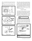
Figure 11 CEILING SUPPORT PIPE
Figure 12 ELBOW OFFSET
All joints (where two pi
p
es are
j
oined) should be secured with
two screws, only on the oute
r
p
ipe, and shall not penetrate
the inner stainless.
Figure 13 FIRESTOP SPACER