


110882-01C
For more information, visit www.desatech.com
For more information, visit www.desatech.com
13
13
INSTALLATION
Continued
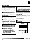
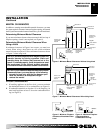
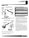
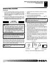
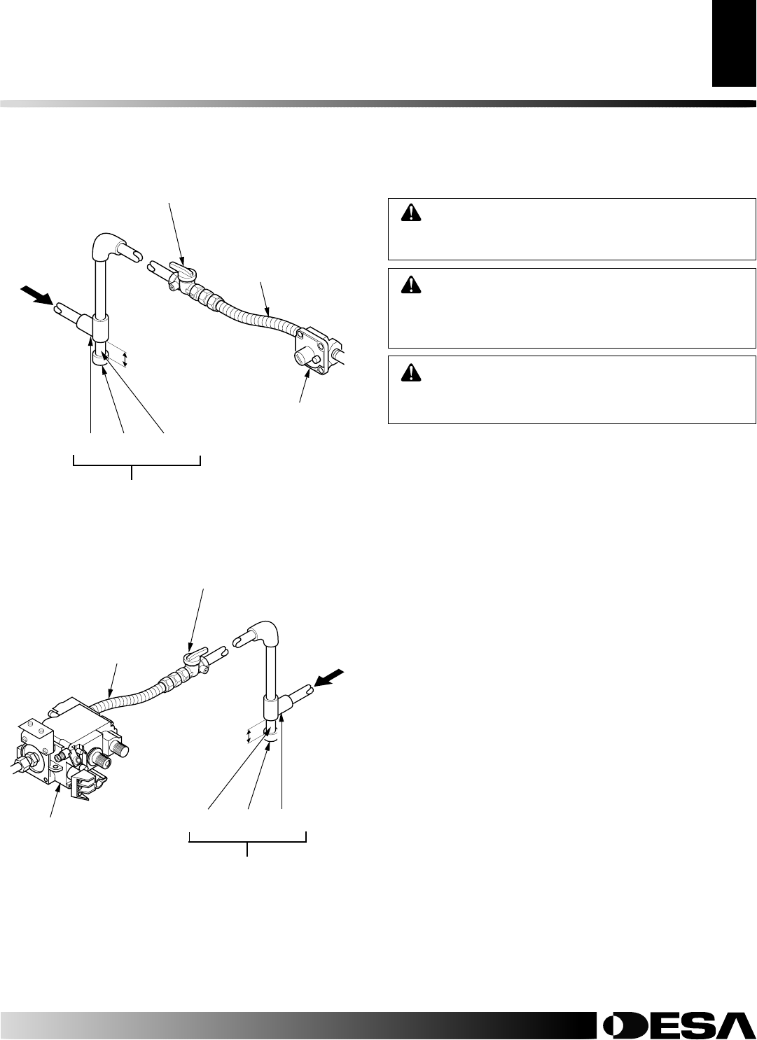
Figure 16 - Gas Connection (Variable Manually-Controlled and
Thermostatically-Controlled Models Only)
* Purchase the optional CSA design-certified equipment shutoff valve
from your dealer. See Accessories, page 36.
**Minimum inlet pressure for purpose of input adjustment.
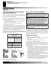
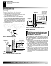
Figure 17 - Gas Connection (Remote-Ready Models Only)
Gas Control
Tee Cap Pipe
Joint Nipple
3" Minimum
Gas Regulator
PROPANE/LP
From External
Regulator
(11" W.C.**
to 14" W.C.
Pressure)
CSA Design-Certified Equipment
Shutoff Valve With 1/8" NPT Tap*
Approved Flexible
Gas Hose (if allowed
by local codes)
Sediment Trap
NATURAL
From Gas
Meter
(5" W.C.**
to 10.5" W.C.
Pressure)
Pipe Cap Tee
Nipple Joint
3" Minimum
Sediment Trap
PROPANE/LP -
From External
Regulator
(11" W.C.**
to 14" W.C.
Pressure)
NATURAL -
From Gas
Meter
(5" W.C.**
to 10.5" W.C.
Pressure)
CSA Design-Certified Equipment
Shutoff Valve With 1/8" NPT Tap*
Approved Flexible
Gas Hose (if allowed
by local codes)
WARNING: Test all gas piping and connections,
internal and external to unti, for leaks after installing
or servicing. Correct all leaks at once.
WARNING: Never use an open flame to check for
a leak. Apply a noncorrosive leak detection fluid to all
joints. Bubbles forming show a leak. Correct all leaks
at once.
CAUTION: Make sure external regulator has been
installed between propane/LP supply and heater. See
guidelines under
Connecting to Gas Supply
, page 12.
Pressure Testing gas Supply Piping system
Test Pressures In Excess Of 1/2 PSIG (3.5 kPa)
1. Disconnect appliance with its appliance main gas valve (control
valve) and equipment shutoff valve from gas supply piping sys-
tem. Pressures in excess of 1/2 psig will damage heater regulator.
2. Cap off open end of gas pipe where equipment shutoff valve
was connected.
3. Pressurize supply piping system by either opening propane/LP sup-
ply tank valve for propane/LP gas or opening main gas valve lo-
cated on or near gas meter for natural gas, or using compressed air.
4. Check all joints of gas supply piping system. Apply noncorrosive
leak detection fluid to all joints. Bubbles forming show a leak.
5. Correct all leaks at once.
6. Reconnect heater and equipment shutoff valve to gas supply.
Check reconnected fittings for leaks.
Test Pressures Equal To or Less Than 1/2 PSIG (3.5 kPa)
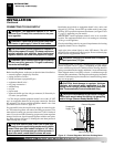
1. Close equipment shutoff valve (see Figure 18, page 14).
2. Pressurize supply piping system by either opening propane/LP sup-
ply tank valve for propane/LP gas or opening main gas valve lo-
cated on or near gas meter for natural gas, or using compressed air.
3. Check all joints from gas meter to equipment shutoff valve for
natural gas or propane/LP supply to equipment shutoff valve
for propane/LP (see Figure 19, page 14). Apply noncorrosive
leak detection fluid to all joints. Bubbles forming show a leak.
4. Correct all leaks at once.
CHECKING GAS CONNECTIONS
INSTALLATION
Connecting to Gas Supply (Cont.)
Checking Gas Connections