


110882-01C
For more information, visit www.desatech.com
For more information, visit www.desatech.com
14
INSTALLATION
Continued
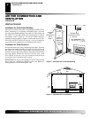
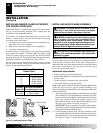
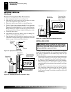
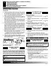
Figure 18 - Equipment Shutoff Valve
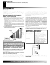
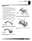
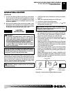
Figure 19 - Checking Gas Joints (Propane/LP Only)
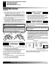
Thermostat Gas
Valve or Control
Valve Location
Propane/LP
Supply Tank
Equipment
Shutoff Valve
ON
POSITION
OFF
POSITION
Open
Closed
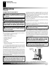
Equipment
Shutoff
Valve
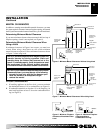
Equipment
Shutoff Valve
Thermostat Gas
Valve or Control
Valve Location
Gas Meter
Pressure Testing Heater Gas Connections
1. Open equipment shutoff valve (see Figure 18).
2. Open main gas valve located on or near gas meter for natural
gas or open propane/LP supply tank valve.
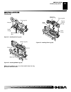
3. Make sure control knob of heater is in the OFF position.
4. Check all joints from equipment shutoff valve to thermostat
gas valve (Thermostat-Controlled Models), to control valve
(Manually-Controlled Models), or to gas control (Remote-
Ready Models) (see Figures 19 and 20). Apply noncorrosive
leak detection fluid to all joints. Bubbles forming show a leak.
5. Correct all leaks at once.
6. Light heater (see Operating Heater, pages 16 through 21).
Check all other internal joints for leaks.
7. Turn off heater (see To Turn Off Gas to Appliance, page 17 for
Thermostat-Controlled models, page 18 for Manually-Controlled
Models, or page 20 for Remote-Ready Models).
Figure 20 - Checking Gas Joints (Natural Gas Only)
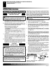
INSTALLING LOGS
WARNING: Failure to position the parts in accor-
dance with these diagrams or failure to use only parts
specifically approved with this heater may result in
property damage or personal injury.
Each log is marked with a number. These numbers will help you
identify the log when installing. It is very important to install these
logs exactly as instructed. Do not modify logs. Only use logs
supplied with heater.
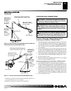
1. Place front log (#1) on top of the grate. Make sure the notches
in the bottom of the log fit over the grate prongs (see Figure
21, page 15). Push back of logs flush with metal grate bars.
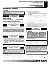
2. Rest middle log (#2) behind metal posts on grate assembly.
Make sure the grooves in the bottom of the log fit over the
grate. Bring the log forward next to the metal posts (see Figure
22, page 15).
3. Slide the grooves in the back of the rear log (#3) against the
rear grate prongs. Make sure the log fits securely over the
prongs (see Figure 23, page 15). Make sure log is completely
vertical and not leaning in toward burner where the flame will
touch the log.
INSTALLATION
Checking Gas Connections (Cont.)
Installing Logs