28
Fuel Piping
SECTION VII - Fuel Piping
Gas Supply Piping Connection
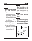
The gas supply piping must be installed
in accordance to all applicable local,
state and national codes and utility
requirements.
1. Remove the burner jacket hood. Refer to
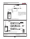
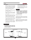
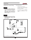
Fig. 15 to pipe gas supply to the burner.
a. Install a pipe union at the factory sup-
plied gas nipple, for ease of service.
b. Install a manual shutoff valve in the gas
supply piping as shown in Fig. 15. For
installations in Canada the installer
must tag and identify the main shutoff
valve.
c. Install a drip leg on the gas supply line
prior to connecting to the ELITE gas
train as shown in Fig. 15.
2. Support the gas piping using hangers. Do
not support the piping by the unit or its
components.
3. Purge all air from the gas supply piping.
4. Before placing the ELITE into operation,
check and test all connections for leaks.
Close the manual shutoff valve during
any pressure test with less than 13”w.c..
Disconnect the ELITE and its gas valve
from the gas supply piping during any
pressure test greater than 13”w.c..
Do not check for gas leaks with an open
flame. Use a gas detection device or bub-
ble test. Failure to check for gas leaks
can cause severe personal injury, death
or substantial property damage.
5. Use pipe dope compatible with natural and
propane gases. Apply sparingly only to the
male threads of pipe joints so that pipe
dope does not block gas flow.
Failure to apply pipe dope as detailed
above can result in severe personal
injury, death or substantial property
damage.
Use a two-wrench method of tightening
gas piping near the unit and its gas valve.
Use one wrench to prevent the gas valve
line connection from turning and the sec-
ond to tighten adjacent piping. Failure
to support the gas valve connection pip-
ing could damage the valve and the gas
line components.
WARNING
WARNING
WARNING
NOTICE
Fig. 15: Recommended Gas Supply Piping


