


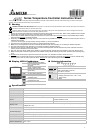

Storage temperature -20°C ~ +65°C
Operation altitude Less than 2,000m
Ambient humidity 35% ~ 85% RH (non-condensing)
Panel protection level IP65
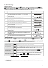
Operation Instructions on Keys!
Switching Modes
DTD is in operation mode (the first level) when the power is switched on. Press
once to switch to the regulation mode (the second
level), or press
for more than 3 seconds in operation mode to switch to the initial setting mode (the third level). Press once in
other screens to return to the operation mode.
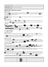
Switching Functions
Press
in each mode to select functions. Press once to switch to the next function, or return to the first function when press
in the last function.
Modifying Settings
Select the item to be set up by using
and . Next, press . If the item to be set up is a value, the last digit of the SV will
flash. If you press
to select parameters, the SV will flash. Press to increase the value of the digit or select parameters. When
setting up the value, press
to left shift to the digit to be modified.
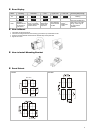
Examples
1. DTD from STOP to RUN:
Press once and select parameter . SV will display . Press and will flash.
Press
to save the setting and will stop flashing.
2. Modifying SV from 80 to 120:
Press and display 0080 (the last digit in right hand side 0 will flash). Press once and 8 will
flash. Next, press
4 times and “2” in the display 0020 will flash. Press once and the 100s digit 0 will flash. Press
once and ”1” in the display 0120 will flash. Press
to complete and save the setting.
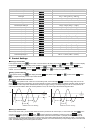
Input Settings!
Setting up Input Type
When DTD is switched on, SV will display the type of the input sensor (default K1 = thermocouple type). Press
for more than 3
seconds in the operation mode and PV will display the parameter
. Press to select the sensor types (see the table below) an
press
d
to complete and save the setting. The screen will return to the screen of operation mode.
If the setting is current input, a 249 resistor has to be connected to the current input terminals.
Setting up Input Unit
In the operation mode, press
for more than 3 seconds and PV will display the parameter . Press once to select the
unit. If the input type is thermocouple or platinum resistance, the PV will display
. In this case, press to select the temperature
unit (°C or °F). If the input type is an analog input, the PV will display
. In this case, you can set up the position of the decimal point
for the analog input. Press
to complete and save the setting.
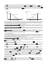
Setting up Input Range
After you complete setting up the input unit, press
once to display the parameter . Use and to set the maximum
value for the temperature range. Press
again to display the parameter , and use and to set the minimum value
for the temperature range. The default range is the maximum range measurable (see the table below) and both parameters cannot
exceed this range. When PV exceeds the range, PV will flash and DTD will stop its operation.
When in analog input, the temperature range also refers to the maximum and minimum input values. For example, when 4 ~20mA input is
adopted,
= 2,000, = 400. That is to say, PV = 1,200 refers to the input is 12mA and the unit is 0.01mA.
Adjusting Input Inaccuracy
When there is the need to correct the measured input PV, press
once in the operation mode to enter the regulation mode. Press
repeatedly until the parameter of input compensation value appears. Modifying this parameter will make the PV = measured
value + input compensation value. Press
again to display the parameter of input gain and make PV = measured value × (1 +
input gain/1,000) + input compensation value. Press
again and display the parameter of software filter (default = 2).
Increase this parameter to enhance the stability of the PV;
however, this will result in slow reaction to the input value.
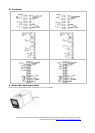
Input Sensor Type Display Temperature Range
4 ~ 20mA input
-999 ~ 9,999
0 ~ 20mA input
-999 ~ 9,999
0V ~ 10V input
-999 ~ 9,999
2