


Parameters P, I and D can be set up manually or auto-tuned by DTD. Follow the steps below for the auto-tuning.
Press
in the operation mode and PV will display the parameter . In RUN state , set the parameter to and DTD
will perform an auto-tuning. The AT indicator will flash and after the setup is completed, the AT indicator will be off. The PID parameters
will be written in automatically and saved. To set up the parameters manually, enter the regulation mode and select the parameter
.
Press
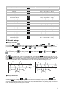
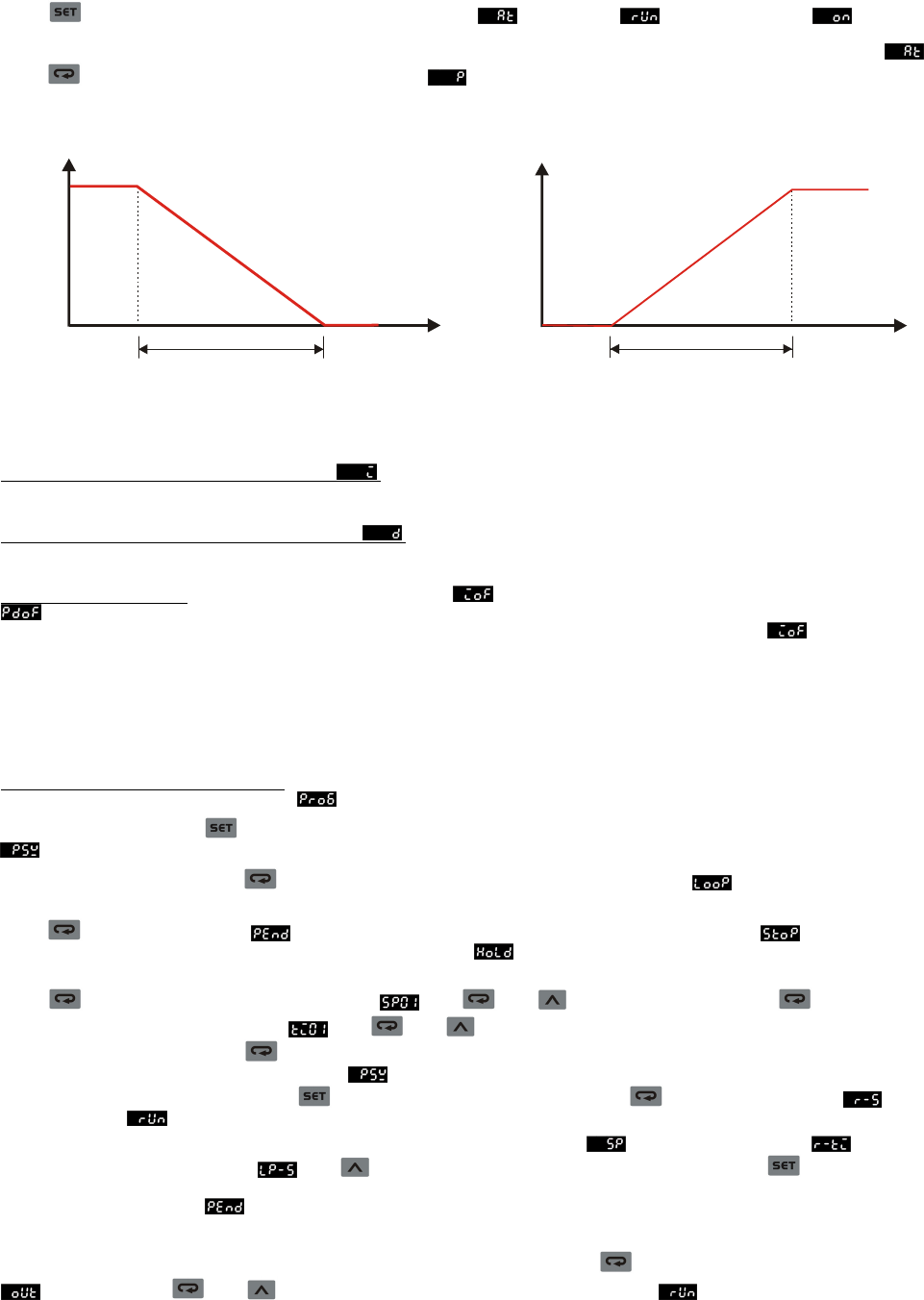
once to display the parameter of proportion band , indicating the range where P control is enabled. See the diagrams
in the next page.
100%
0%
SV-Pb
SV
Proportion band
(
Pb
)
(Output percentage)
Heating process
(Temperature)
100%
0%
SV+Pb
SV
Proportion band
(
Pb
)
(Output percentage)
Cooling process
(Temperature)
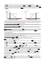
The bigger the parameter P, the less possible that the heating will exceed the SV and the longer it will take for the temperature to reach
SV. This is suitable for the control system with faster reaction speed. On the contrary, the smaller the parameter P, the more possible that
the heating will exceed the SV and the shorter it will take for the temperature to reach SV; however, unstable control is more likely to
occur. Smaller P is suitable for the control system with slower reaction speed.
How to set up the parameter of integration time I
: The bigger the value I, the longer the integration time, as well as the time to
reach the SV. Unstable control is also less likely to occur. On the contrary, the smaller the value I, the shorter the integration time, as well
as the time to reach the SV. Unstable control is thus more likely to occur.
How to set up the parameter of differentiation time D
: The bigger the value D, the faster reaction speed and repression power DTD
has for the external interference. However, if D is too big, the repression power that is also too big will result in out of control of the
situation.
Parameters for PID control:
The default integration output volume is to allow the temperature to fast reach the SV. The parameter
is for compensating the steady error in PD control. The two parameters are the output percentages when the input reaches the SV.
Assume the output percentage is 20% when PV = SV, the best setting for this parameter is 20.0. The parameter
can be a
reference value when being auto-tuned. It can also be adjusted manually.
PID Programmable Control!
PID programmable control offers 8 steps for you to plan for the temperature control program. You can set up your own number of steps
and times of execution and directly monitor the current executing step, remaining time and the current SV. There is only 1 group of PID
parameter settings and by the first step, you can directly control the temperature to the SV. You can also set up the control status that
after the program ends, DTD will either stop the output or stay at the last SV.
Setting up the parameters in the program:
To set up the parameters in the program, you have to first enter the initial setting mode and set
the control mode as programmable control
to further display the parameters which you can set up.
In the operation mode, press
and enter the regulation mode. PV will display the parameter of the number of steps to be executed
. Maximum 8 steps can be planned in this parameter.
After the setup is completed, press
to display the parameters for setting up the execution loops . The range of this parameter
is 1 ~ 99, e.g. 2 means executing twice.
Press
to setup the parameter for the action of DTD after the program ends. Set this parameter as , indicating that the
control output will stop after the program ends. Set this parameter as
, indicating that DTD will stay at the last step before the
program ends.
Press
and display the parameter of SV of step 1 . Use and to set up the SV. Next, press to display the
parameter of the executing time of step 1
. Use and to set up the time (unit: minute; Max. 9,999 minutes). After the
setup of step 1 is completed, press
to set up the parameters (SV and executing time) of the next step. Please note that the number
of steps is decided by the setting of the parameter
. The number of steps that exceeds the setting will not be displayed on the
screen of DTD during the operation. Press
to return to the operation mode and press to display the parameter . Set
this parameter as
and execute the control. DTD does not offer pause function; all executions start from step 1.
In the operation mode, on the SV display, you can monitor the present value (default)
, remaining executing time , or the
executed number of loops and steps
. Use to switch between different monitoring modes and press to display the
selected monitoring mode. When the execution of the program ends, the remaining executing time will be displayed as “0” and the
executed loops and steps as
.
Setting up Manual Control
Select manual control in the control mode and set up the control cycle first. Next, press
repeatedly in the operation mode until
is displayed. Use and to modify the output percentage. During the execution , the output percentage will vary
upon different output percentage settings. The output setting will be saved and the saved setting will be adopted next time when DTD is
switched on. The default setting is 0%.
4