


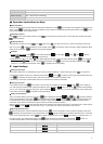
Input Sensor Type Display Temperature Range
0V ~ 5V input
-999 ~ 9,999
0 ~ 70mV input
-999 ~ 9,999
Cu50 type
-50
o
C ~ 150
o
C (-90.0
o
F ~ 302.0
o
F)
Pt100 type 2
-99.9
o
C ~ 600.0
o
C (-99.9
o
F ~ 999.9
o
F)
Pt100 type 1
-200
o
C ~ 600
o
C (-360
o
F ~ 1,112
o
F)
JPt100 type
-20.0
o
C ~ 400.0
o
C (-36.0
o
F ~ 752.0
o
F)
Thermocouple TXK type
-200
o
C ~ 800
o
C (-360
o
F ~ 1,472
o
F)
Thermocouple U type
-200
o
C ~ 500
o
C (-360
o
F ~ 932
o
F)
Thermocouple L type
-200
o
C ~ 850
o
C (-360
o
F ~ 1,562
o
F)
Thermocouple B type
100
o
C ~ 1,800
o
C (180
o
F ~ 3,272
o
F)
Thermocouple S type
0
o
C ~ 1,700
o
C (0
o
F ~ 3,092
o
F)
Thermocouple R type
0
o
C ~ 1,700
o
C (0
o
F ~ 3,092
o
F)
Thermocouple N type
-200
o
C ~ 1,300
o
C (-360
o
F ~ 2,372
o
F)
Thermocouple E type
0
o
C ~ 600
o
C (0
o
F ~ 1,112
o
F)
Thermocouple T type 2
-99.9
o
C ~ 400.0
o
C (-99.9
o
F ~ 752.0
o
F)
Thermocouple T type 1
-200
o
C ~ 400
o
C (-360
o
F ~ 752
o
F)
Thermocouple J type 2
-99.9
o
C ~ 999.9
o
C (-99.9
o
F ~ 999.9
o
F)
Thermocouple J type 1
-200
o
C ~ 1,200
o
C (-360
o
F ~ 2,192
o
F)
Thermocouple K type 2
-99.9
o
C ~ 999.9
o
C (-99.9
o
F ~ 999.9
o
F)
Thermocouple K type 1
-200
o
C ~ 1,300
o
C (-360
o
F ~ 2,372
o
F)
Control Settings!
Setting up Control Mode
In the operation mode, press
for more than 3 seconds and PV will display the parameter . Press for 4 times to display
the parameter
. The default setting of this parameter is “On/Off control” . Use to select PID control , PID
programmable control
or manual control . Press again and display the parameter for selecting the control
method. You can select heading (default)
or cooling . Press to return to the operation mode.
Setting up RUN and STOP
In the operation mode, press
and display parameter . The default is RUN . Use to select STOP . Press
to complete the setting and the output will be disabled.
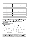
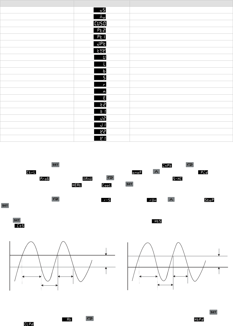
Setting up On/Off Control Parameters
Press
in the operation mode. If DTD is in On/Off heating mode, the PV will display ; if in On/Off cooling mode, the PV will
display
. Modify these parameters to set up the hysteresis of On/Off. The default setting is 0 (without hysteresis). When the output
reaches SV, the control output will be disabled. When the input is bigger (cooling) or smaller (heating) than the SV and hysteresis, the
control output will be enabled. When the On/Off hysteresis is not 0, the control output will be like the diagrams below.
Hysteresis
HtS
OFF
ON
OFF
ON/OFF Control for Heating
SV
Hysteresis
CtS
OFF
ON
ON
ON/OFF Control for Cooling
SV
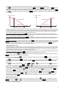
Setting up PID Parameters
When in PID control mode, you have to first decide the On/Off cycle time for the control output, i.e. the control cycle. Press
in the
operation mode and PV will display
. Press 5 times to display the parameters of heating control cycle or cooling
control cycle
. Set up the cycle depending on the reaction speed of the control system. In principle, the faster the reaction, the
shorter the cycle and more accurate the control. A short control cycle indicates that there will be more times of On/Off. If you adopt relay
output, the short cycle will shorten the life span of the relay. Therefore, it is recommended that you adopt voltage output in the PID control
mode. The default setting of the control cycle is 20 seconds.
3