


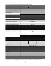
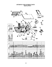
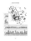
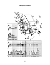
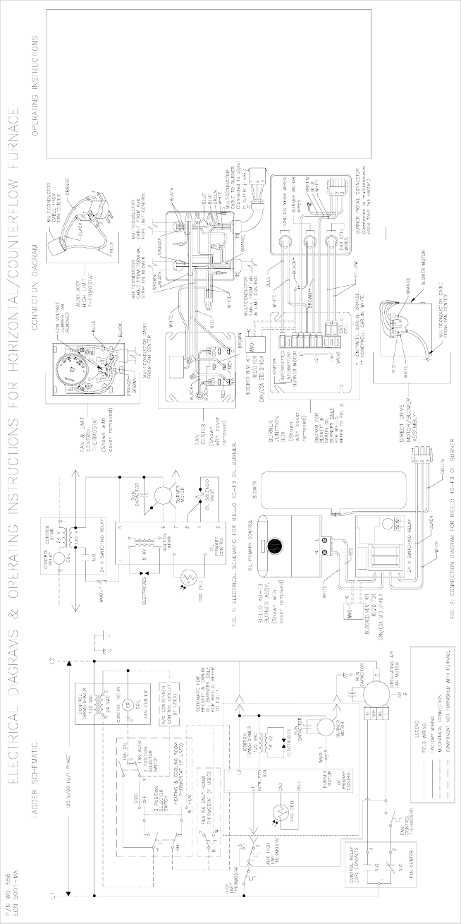
APPENDIX B: ELECTRICAL DIAGRAMS
For your safety, read this information before operating this
furnace.
WARNING: Failure to follow these instructions may
result in a fire or explosion causing property damage,
personal injury, or loss of life.
WHAT TO DO IN THE EVENT OF AN OIL LEAK:
• DO NOT try to operate this or any other nearby appliance.
• If present, close the manual shutoff valve on the oil line.
• Immediately call a qualified heating contractor for service.
• If you cannot reach a qualified heating contractor, call the
fuel oil supplier or the fire department.
DO NOT use this furnace if any component was underwater.
Immediately call a qualified heating contractor to inspect the
furnace and replace any part of the furnace control system
that was underwater.
This furnace does not have a pilot light. It is equipped with
an ignition system that automatically lights the burner. DO
NOT attempt to light the burner by hand.
TO OPERATE THIS FURNACE:
1. Adjust the room thermostat to the lowest setpoint and set
the operating mode, if equipped, to "OFF".
2. Turn off all electric power to the furnace at the
disconnecting switch.
3. Rotate the manual oil shutoff valve to the open or on
position.
4.This furnace is equipped with an electronic ignition system
that automatically lights the burner. DO NOT try to light the
burner by hand.
5. Turn on the electric power to the furnace at the
disconnecting switch.
6. Adjust the room thermostat to the desired setpoint and set
the operating mode, if equipped, to "HEAT".
7. If the furnace will not operate, call a qualified heating
contractor for service.
TO INTERRUPT (STOP) OPERATION OF THIS FURNACE:
1. Adjust the room thermostat to the lowest setpoint and set
the operating mode, if equipped, to "OFF".
2. If service will be performed, turn off all electrical power to
the furnace at the disconnecting switch.
3. Turn the manual oil shutoff valve to the closed or off
position.
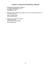
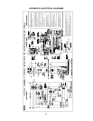
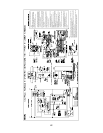
Notes:
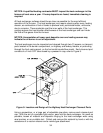
1. Using wirenuts, connect power supply wire L1 to pigtail marked "1" and wire L2 to pigtail marked "2" in fan
center. Connect an earth grounding wire to ground wire terminal in fan center.
2. If any electrical wiring must be replaced, new wiring must have an insulation type rated for 105°C or greater.
3. Use only copper conductors for all field and replacement wiring.
4. For adequate overcurrent protection, maximum acceptable size time delay type fuse or inverse time circuit
breaker is 15 A.
5. Typical room thermostat anticipator setting is 0.1 A.
6. Use Class I type electrical wiring to make thermostat connections to fan center and oil primary safety control.
7. If replacing fan & limit thermostatic control, remove low voltage jumper tab on new control.
8. Electrical schematic shown with heating system, cooling system (if equipped), and fan off.
41