


11
If desired, with the furnace flue elbow turned to the right, the standard furnace top front
panel (p/n 52-17346-1) may be replaced with the top front panel from the rear flue
lowboy model (p/n 52-17383-1). Refer to Appendix D: Replacement Parts for sketches
of these parts. Contact your Crown distributor to purchase this part.
All horizontal sections of the vent connector must slope upward not less than ¼ inch per
foot from the furnace to the vent termination. Long horizontal sections of the venting
system must be supported at least every five (5) feet with metal straps to prevent
sagging of the vent piping. Secure all joints in the vent connector with sheet metal
screws or equivalent fasteners. Vent piping must not be inserted beyond the inside wall
of the chimney flue.
Power (Side-Wall) Venting – Important Note Regarding
c CAUTION: Crown Boiler Company will NOT assume responsibility for damage
to, and deterioration of, exterior building materials, e.g. brick, siding, clapboards,
and etc., in close proximity to the vent terminal due to operation of a power
vented, oil furnace. This policy is applicable regardless of the cause of sooting.
Two (2) problems typically arise when power venting any oil-fired appliance.
1) Soot buildup may occur at an accelerated rate on critical components of the
furnace oil burner, e.g. the primary control flame sensor (“cad cell”), the burner
head, and oil nozzle.
2) Severe damage may occur to external surfaces of the structure in the event the
furnace continually produces a high level of smoke in the flue gases. Excess
smoke and soot can be produced for many reasons, some of which cannot be
successfully controlled by the installer and the appliance manufacturer.
NOTICE: Crown Boiler recommends the use of a chimney to vent residential oil
furnaces. If a power venter must be used, it is the responsibility of the installer
and power venter manufacturer to design, assemble, and demonstrate proper
operation of the power venting system with the furnace.
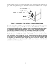
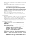
Draft Regulator
A barometric-type, draft regulator is supplied with the furnace. Installation or operating
conditions that produce excess amounts of draft can reduce the heating efficiency of the
furnace. The purpose of the regulator is to adjust and control the flow of flue gases from
the furnace by stabilizing the amount of chimney draft to which the furnace is subjected.
Generally, install the barometric draft regulator in the vent connector as close as
possible to the flue outlet collar of the furnace. However, always refer to the draft
regulator manufacturer’s installation instructions for application specific
recommendations.