


16
Nozzle selection (i.e. heating capacity of the furnace) shall be based on a rate of heat
loss (heating load) calculation for the building. These calculations should be made
according to the manuals provided by the Air Conditioning Contractors of America
(ACCA) or the American Society of Heating, Refrigeration and Air Conditioning
Engineers, Inc. (ASHRAE).
Refer to the Residential Load Calculation, Manual J, from the ACCA, and the ASHRAE
Handbook Fundamentals volume, from ASHRAE, for the recommended procedure to
compute the design heating load of a residence. To obtain copies of these publications
for a fee, contact the ACCA and the ASHRAE at the addresses given in Appendix A of
this manual.
The oil burner is shipped in a separate carton from the furnace. In the field, it is
necessary to mount the oil burner, secure it to the furnace, and connect the wiring
harness to complete the installation. Refer to the following steps.
1) Remove the oil burner from the shipping carton and remove any shipping
materials adhering to the burner.
2) If it is necessary to adjust the heating capacity of the furnace, by changing the oil
burner nozzle, refer to these instructions. Also, consult the oil burner
manufacturer’s operating instructions (included with the burner) for detailed
instructions on this procedure.
a) The oil nozzle is factory installed in the oil burner. To change the oil
nozzle, remove the nozzle through the front end of the burner air tube. (If
the oil burner is already installed, the oil burner can be removed from the
heat exchanger mounting plate to gain access to the nozzle. Alternatively,
the nozzle and electrode assembly may be removed from the rear of the
burner assembly without removing the oil burner from the furnace.)
b) Install an appropriate replacement nozzle of the correct size, spray angle,
and spray type. Refer to the Specification Sheets, in Appendix C of this
manual, for nozzle recommendations.
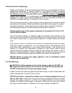
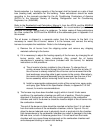
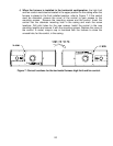
3) The furnace may have been handled roughly while in transit. Under some
conditions, the combustion chamber can shift out of position. Check for proper
alignment of the burner air tube with the circular opening in the combustion
chamber and trial fit the burner to check the insertion depth of the oil burner into
the combustion chamber.
The end of the burner air tube should be inserted no farther than 1/4 inch back
from the inside surface of the combustion chamber, refer to Figure 4. Do not
allow the burner tube/end cone to physically touch or protrude into the chamber.
High temperatures in the combustion chamber can result in damage to the tube,
the end cone, or both. A distance greater than 1/4 inch back from the inside
chamber wall may cause flame impingement on the combustion chamber wall
and subsequent sooting or carbon char buildup.