


Sequence of Operation - Steam Boiler
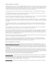
1) When the boiler is energized, 24 volts is immediately applied to terminals “1” (blue) and “4” (yellow) on the vent damp-
er. Assuming that there is no call for heat, and that the damper switch is in the “automatic” position, the damper will close.
On boilers equipped with Hydrolevel CG400A probe type low water cut-offs, voltage is also always applied to terminals
“1” (blue) and “2” (yellow) on the low water cut-off to power the water level sensing circuit.
2) Assuming that water is above the cut-off level, power will appear at terminal “3” on the CG400 LWCO or terminal “1”.
3) Assuming that steam pressure is below the pressure limit setting, power will appear on one side of relay contact 1R1
(Gray lead). Relay 1R is the R8225 mounted under the junction box.
4) A call for heat from the thermostat energizes relay coil 1R causing contacts 1R1 to make. Current then ows through con-
tacts 1R1 to pin terminal “2” (orange) at the vent damper (if used) and the damper opens.
5) Once the vent damper is fully open, an end switch inside the damper will make, energizing pin “3” (red) at the damper.
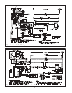
If a vent damper is not present, current ows through the red jumper indicated by Note 2 in Figure A directly to the blocked
vent switch.
6) Current passes from terminal “3” on the vent damper through the blocked vent switch. Under normal conditions, this
switch is made and voltage will therefore immediately appear across terminals “24V” and “24V (GND)” on the ignition
module.
7) Upon application of voltage across the “24V” and “24V (GND)” terminals, the ignition module will start an ignition
spark at the pilot and apply 24 volts across the pilot valve (terminals “PV” and “MV/PV”).
8) Once the pilot is established, the pilot ame will act as a diode, converting the AC current at the electrode to a half wave
DC current at the pilot’s ground strap. This DC current ows through the boiler to the “GND (BURNER)” connection on
the ignition module. For the ignition module to recognize that a pilot ame is present, the DC current owing into this ter-
minal must be in excess of approximately 1.0 uA.
9) Once the ignition module detects the presence of a pilot ame, voltage is applied across the main valve (terminals “MV”
and “MV/PV”), opening the valve and establishing main ame.
10) The way in which the ignition module handles failure to establish pilot or the loss of an already established pilot
depends upon the exact ignition module supplied with the boiler. For more information on module operation, consult the
ignition module instructions supplied with the boiler or the local Crown representative.
Safety Control Operation - Steam Boilers
Hydrolevel CG400A Low Water Cut-off - Interrupts burner operation if the water in the boiler drops below a safe level.
As the water drops past the cut-off point, the amber lamp on the CG400 will glow. The CG400 will interrupt power to the
burners 15 seconds after the water level drops past the cut-off point. This feature prevents short cycling of the burners due
to a bouncing water line. The burners will then remain off until 30 seconds after the water level has been raised above the
cut-off point.
The CG400 is also equipped with a feature which will shut down the burners after they have been ring for 20 minutes,
regardless of the water level status. The CG400 then keeps the burners off for 90 seconds, allowing the water level and any
foam which is present to settle. During this 90 second interval, the green LED on the CG400 will glow. If the water level is
still above the cut-off line at the end of this 90 second interval, the CG400 will restart the burners.
The vent damper will close when the low water cut-off interrupts burner operation.
Pressure Limit Control - Interrupts burner operation when the pressure in the boiler exceeds the “Cut-in” setting plus the
differential setting. The “Cut-in” setting is shown on the outside of the control and is adjusted using the screw on the top
of the control. The differential is adjusted using the white thumb wheel on the inside of the control. Burner operation is
restored when the pressure in the boiler drops to the “Cut-in” pressure.
Blocked Vent Switch - Automatically interrupts burner operation in the event of a blocked vent condition. This switch is
5