


WARNING
All wiring and grounding must be done in accordance with the authority having jurisdiction or, in the absence of such
CAUTION
Make sure that damper and BVS harnesses are secured so that they do not come in contact with draft hood or steam piping.
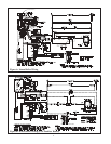
XI Control System Wiring
Wire the boiler in accordance with the following instructions rather than those in the installation manual. Provide the boiler
with a dedicated branch circuit with a fused disconnect. The minimum rating of this circuit must be 15A. Wire the boiler
using the appropriate wiring diagram shown in Figures A-C in this supplement. In addition, note the following:
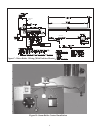
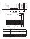
1) Steam boiler wiring is shown in Figure A. The junction box, transformer, and thermostat relay are prewired with all low
voltage wire harnesses, except the damper harness (if used).
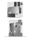
a) Mount the junction box assembly to the side jacket panel as shown in Figure D using two #10 x 1/2” sheet metal
screws.
b) Connect the gray limit harness to terminals R and B on the L404 pressure limit.
c) Mount the blocked vent switch (BVS) to the draft hood as shown in Figure E using two #10 x 1/2” sheet metal
screws. Route the red BVS harness along the side of the boiler as shown in Figure D and connect the pair of fully
insulated quick connects to the BVS.
d) Route the other end of the BVS harness to the ignition module . Connect the fully insulted quick connect to the
“24 Volt” terminal. Connect the uninsulated connector to the “24 V Ground” piggy back terminal. Secure the BVS
harness to the jacket with the nylon clips provided as shown in Figure D.
e) If a damper is installed, remove the red jumper wire inside the junction box that is indicated by Note #2 in Figure A.
Connect the damper harness to the wiring in the junction box as shown in Figure A. Route the damper harness to the
damper as shown in Figure D, using care to make sure that it does not come in contact with the draft hood or steam
piping.
f) If a redundant LWCO and/or pressure limit are used, wire them so that they interrupt 120VAC power to the boiler.
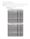
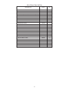
2) Water Boiler wiring is shown in Figure B for boilers without a tankless heater and in Figure C for boilers with a tankless
heater. The blocked vent switch (BVS) wire harness is factory wired to B1 and B2 on the “aquastat” (L8148E or L8124E).
a) Mount the aquastat to the control well.
b) Mount the blocked vent switch (BVS) to the draft hood as shown in Figure E using two #10 x 1/2” sheet metal
screws. Route the red BVS harness along the side of the boiler as shown in Figure F and connect the pair of fully
insulated quick connects to the BVS.
c) Route the other end of the BVS harness to the ignition module . Connect the fully insulated quick connect to the
“24 Volt” terminal. Connect the uninsulated connector to the “24 V Ground” piggy back terminal. Secure the BVS
harness to the jacket with the nylon clips provided as shown in Figure F.
d) A vent damper cannot be used on boilers equipped with tankless heater. If a damper is installed on a boiler without
the tankless heater, remove the jumper plug inside the L8148E aquastat. Plug the 6-pole end of the damper harness
into the aquastat. Plug the 4-pole end of the harness into the damper. Route the damper harness to the damper as
shown in Figure F, using care to make sure that it does not come in contact with the draft hood.
e) If a LWCO and/or redundant temperature limit are used, wire them so that they interrupt 120VAC power to the
boiler.
3) Provide a Class II circuit between the boiler and the thermostat. Make thermostat connections to the boiler in accordance
with Figure A-C.
4) Make 120VAC connections to the boiler in accordance with Figure A-C.
3