


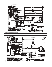
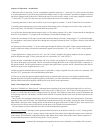


6) Once the ignition module detects the presence of a pilot ame, voltage is applied across the main valve (terminals “MV”
and “MV/PV”), opening the valve and establishing main ame.
7) The way in which the ignition module handles failure to establish pilot or the loss of an already established pilot depends
upon the exact ignition module supplied with the boiler. For more information on module operation, consult the ignition
module instructions supplied with the boiler or the local Crown representative.
8) The boiler will re until the boiler water temperature is approximately equal to the low limit setting. Once the water
temperature reaches this point, “R” and “B” open and “R” and “W” make. At this point, a call for heat from the thermostat
will energize 1R, making contacts 1R1 and 1R2. Contacts 1R1 energize the circulator. Contacts 1R2 switch current from
the “hot” side of the transformer secondary to the high limit switch. If the high limit is made, current ows to terminal “B1”
and the ignition sequence is then the same as it is for a call for burner operation from the low limit (see (3) above).
Safety Control Operation - Water Boilers
High Limit - Interrupts main burner operation when the supply water temperature exceeds set point. Maximum allowable
temperature is 250°F. If the high limit opens, the vent damper will close if the damper switch is in the “automatic” posi-
tion. The circulator will continue to operate as long as there is a call for heat, regardless of the status of the high limit (if
the boiler is equipped with a tankless coil, the low limit switch will prevent the circulator from operating if the boiler water
temperature is too low). Burner operation automatically resumes when the supply water temperature falls below set point.
Blocked Vent (“Spill”) Switch - Automatically interrupts main burner operation in the event that ue gas spills from
the draft diverter opening. This switch is equipped with a reset button which must be pressed to restore normal burner
operation. An open blocked vent switch is indicative of a problem with the vent system. If the blocked vent switch opens,
the cause of the venting problem must be found and corrected by a qualied gas service technician before the blocked vent
switch is reset.
XII - Start-up and Checkout - In addition to start-up procedure shown in the installation manual, also verify
that the vent damper (if installed) is in the open position when the burners are ring.
XIII Service in Maintenance - Refer to installation manual.
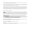
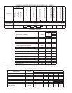
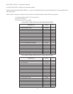
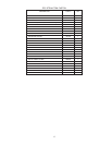
XIV Parts - Parts lists on following pages describe cartons and components unique to the 32-380ECS and 32-475ECS.
Refer to the installation manuals where indicated for universal parts lists.
9