


VII Venting
Refer to installation manual. Vent sizing for the 32-380ECS should always be done in accordance with the National Fuel
Gas Code.
A vent damper can be installed on any 32-380ECS or 32-475ECS equipped with a 24 volt control system except for those
with tankless heaters. If a vent damper is installed, the following components are required:
• Efkal Model GVD-12 Vent Damper: Crown PN 96-038
• Damper Harness (Steam Boilers): Crown PN 9601300
• Damper Harness (Water Boilers): Crown PN 9601550
To install the damper:
1) Open vent damper carton and remove installation instructions. Read the instructions thoroughly before proceeding. Verify
that vent damper is same size as draft diverter outlet (12”). Unpack vent damper carefully. Do not force closed damper
blade. Forcing vent damper closed may result in damaged gear train.
2) Vent damper is factory shipped having approximately ¾” diameter hole in the vent damper blade, which must be left
open even though this boiler is equipped with an intermittent ignition system.
3) Mount the vent damper on the ue collar without modication to either and secure with sheet metal screws. Make
sure screws do not interfere with damper blade operation. Vent damper blade position indicator must be visible to users.
Maintain at least 6 inches between the vent damper device and combustible construction. Also make sure that there is
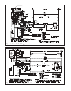
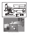
adequate access to the vent damper for servicing. Figures D and F in the Wiring section show typical damper orientation.
4) Install vent connector pipe and vent ttings from vent damper outlet to chimney or gas vent. Secure with sheet metal
screws and support as required.
5) See the Wiring section of this supplement for instructions on making damper electrical connections.
VIII Steam Boiler Piping and Trim Installation
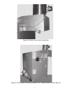
Refer to installation manual. The #67 low water cut-off (LWCO) cannot be used as the primary (operating) LWCO on the
380ECS or 475ECS. Instead, a Hydrolevel CG400 is installed in tapping “G” (Figure 22). A #67 LWCO can be used as
a redundant LWCO (with or without manual reset) in tappings “E” along with the level glass. The CG400 supplied with
this boiler uses the same angeless probe, and is mounted on the boiler in the same manner, as the CG450 described in the
installation manual at the top of page 28. Install the 32-380ECS near boiler piping in accordance with that shown for the
32-475 in Figure 27a in the installation manual.
IX Water Boiler Piping
Refer to installation manual. Boilers covered by this supplement which are not equipped with a tankless heater are supplied
with a Honeywell L8148E limit control installed in Tapping “C” (Figure 29) using the 1/2” well and 1/2 x 1-1/2” bushing
supplied. Boilers equipped with a tankless heater are supplied with a Honeywell L8124E, which is installed using a 3/4”
well in the tankless heater. The L4006A shown in the installation manual is not used.
X Gas Piping - Refer to installation manual
WARNING
Install the vent damper directly on top of the boiler so that it is servicing only the boiler.
2