


CRESTRON GREEN LIGHT™ Architectural Dimming
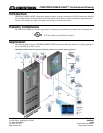
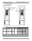
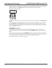
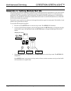
Connector Wiring
RED
WHITE
BLUE
BLACK
RED
WHITE
BLUE
BLACK
OVERRIDE:
FROM OTHER CABINET;
FROM ALARM, ETC.
(OPTIONAL); TO OTHER
CABINET(S) IF NECESSARY
POWER:
24 VDC JUMPERED FROM NET
PORT or EXTERNAL SUPPLY.
PROVIDES CRESNET POWER
TO THE MODULES
NET:
TO CONTROL SYSTEM AND
OTHER CRESNET DEVICES
MODULES:
TO GLX MODULES
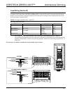
NET Port Wiring
When wiring the supplied NET connectors for connection to a Crestron control system or other device on the
Cresnet network, use Crestron certified wire such as CRESNET-NP or CRESNET-P.
To ensure optimum performance over the full range of your installation topology, use Crestron certified wire.
Failure to do so may incur additional charges if support is required to identify performance deficiencies because
of using improper wire.
When daisy-chaining connections between NET ports, strip the ends of the wires carefully to avoid nicking the
conductors. Twist together the ends of the wires that share a pin on the network connector, insert the connection
into the Cresnet connector, and tighten the retaining screw. Repeat the procedure for the other three conductors.
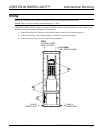
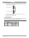
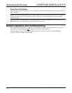
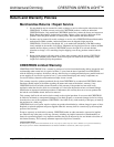
POWER Port Wiring
Low voltage (24 VDC) power must be supplied to the modules either internally via devices connected to the
NET port or externally via a Cresnet power supply connected to the POWER port.
To power the modules internally from line power, install a jumper from the INT pin on the supplied POWER
connector to the EXT pin on the POWER connector as shown in the following diagram.
Providing Cresnet Power Internally
When a lighting module is powered from line power, the module’s PWR LED will illuminate.
Installation Guide – DOC. 6688A CRESTRON GREEN LIGHT Architectural Dimming • 9