


Architectural Dimming CRESTRON GREEN LIGHT™
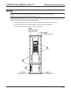
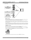
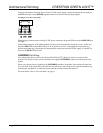
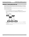
The GLX-DIMFLV8 also requires wiring the terminals for 0-10 VDC control wire. Refer to the following
diagram when connecting the dimmable ballast. Each control wire terminal accepts one 12 – 28 AWG wire.
0-10 VDC Control Wiring for GLX-DIMFLV8 Only
TO "+" ON 4-WIRE LOADS (PURPLE)
TO "-" ON 4-WIRE LOADS (GRAY)
2. Test the circuit for electrical faults by turning on each circuit breaker, checking that the breakers do not
trip, and that power is delivered to the proper loads.
3. Turn off the circuit breaker(s) and remove all jumpers.
4. Turn on the circuit breakers.
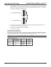
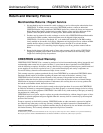
Control Wiring (Section C)
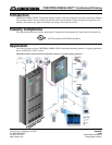
The bottom of the cabinet contains Cresnet
®
connections for interfacing to the rest of the Crestron
®
control system.
It also provides an override input which can be tied to devices such as the GLS-PLS-120/277 phase-loss sensor, or
other devices that provide a dry contact closure (manual switch, fire alarm relay, etc.).
NOTE: Interface connectors for NET (x2), POWER (x3), and OVERRIDE (x3) ports are provided.
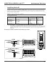
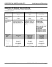
Wire Gauge and Torque Values
TERMINAL CONNECTOR MAX
WIRE RANGE
TORQUE STRIP
LENGTH
NET 26-12 AWG
4.43 lb-in
(0.5 Nm)
1/4”
(6 mm)
POWER 26-12 AWG
4.43 lb-in
(0.5 Nm)
1/4”
(6 mm)
OVERRIDE 26-12 AWG
4.43 lb-in
(0.5 Nm)
1/4”
(6 mm)
8 • CRESTRON GREEN LIGHT Architectural Dimming Installation Guide – DOC. 6688A